I bought my 2001 Deauville in May last year (2013) from a private seller in the UK. The bike was minded like a baby from new and had only 24,000km on it when I bought it. It started life as a shop-floor display model in Germany (hence the clocks being in kilometres). The first owner was English and imported it to the UK. The guy I bought it from was the second owner and bought it because he knew the bike from seeing it in the bike shop where it was serviced and he knew it had been very well looked after.
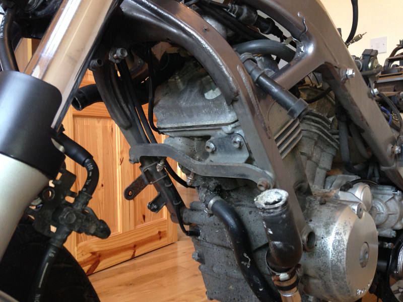
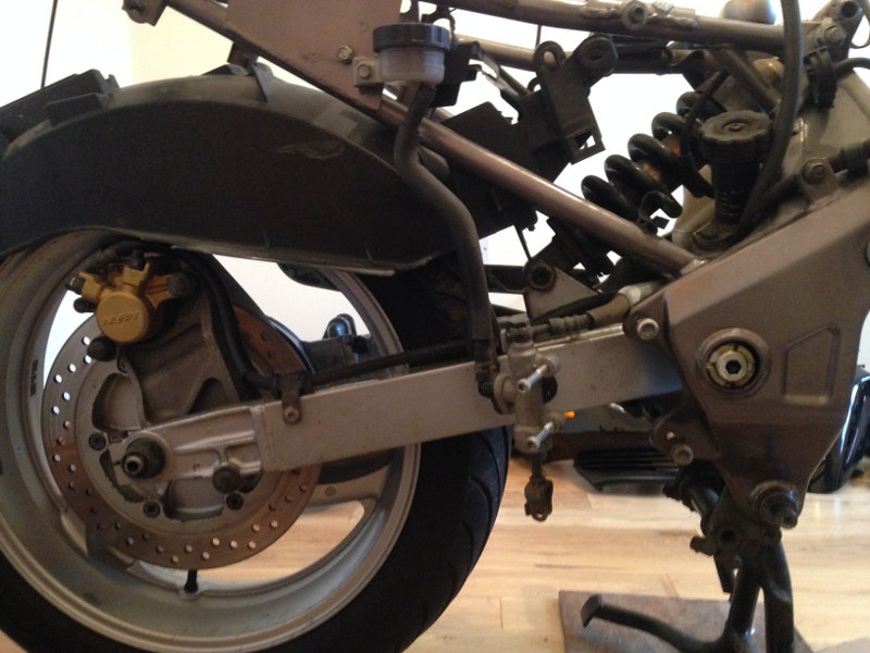
As far as I know, a lot of the screws and bolts on the bike haven't been opened since the bike was built because the mileage is so low and the bike never gave any trouble. It has always been garaged, so there's no rust anywhere on the bike, but age has made some of the bolts a bit stiff, so I've decided to strip the bike down and clean and lubricate everything as I rebuild it. There are 32,000km on the clock now and the valve clearances are due to be adjusted at 36,000km, so I'll do that while I have it stripped. Aesthetically, the only flaw is that stones thrown up by the front wheel have chipped the paint off the front of the engine. I'll repaint the affected parts of the engine while I have the engine out.
That's the plan, anyway. I'll see how it works out over the next few weeks. I'm also planning a few mods, but I won't ruin the surprise by telling what they are in advance. :P
Day 1:
The first job was to strip all the fairings and plastic bits off the bike so that I can fit it into the house and work on it in my spare bedroom, so I can work on it in the comfort of a heated room, rather than a cold shed. I did this job the weekend before Christmas, but didn't get a chance to do the write-up until now.
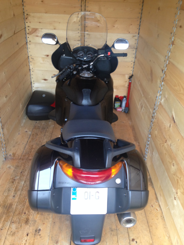
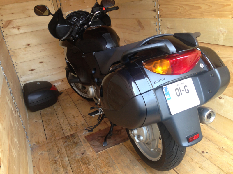
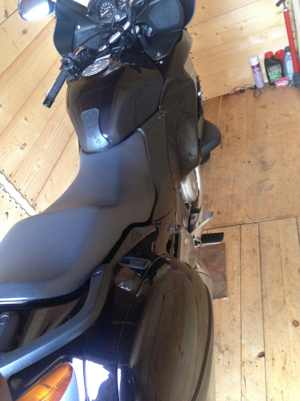
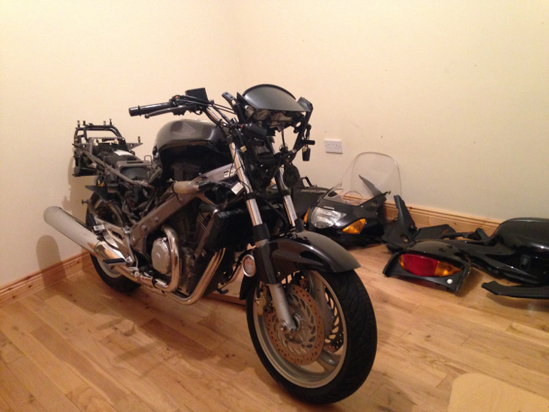
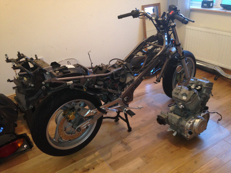
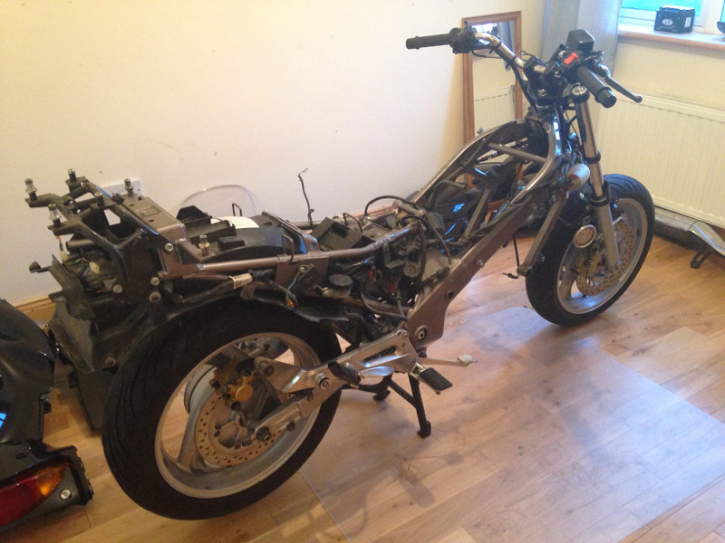
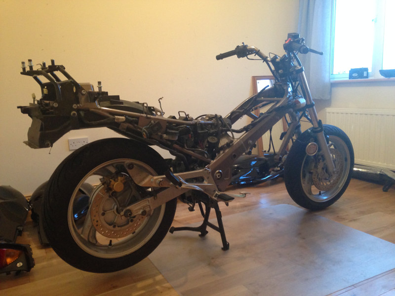
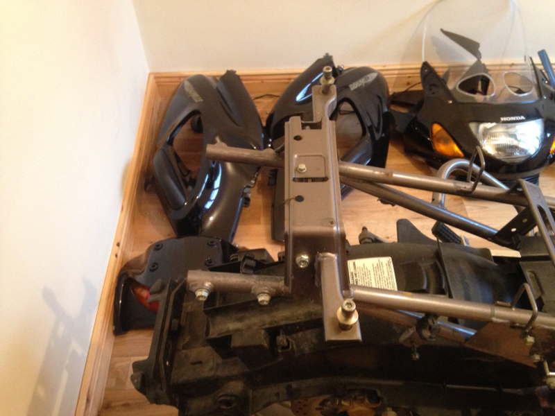
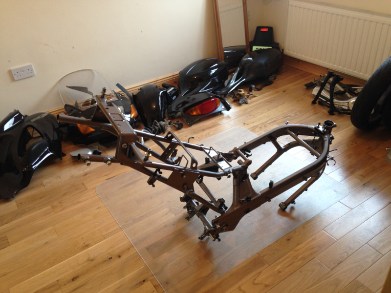
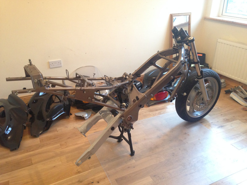
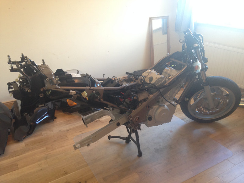
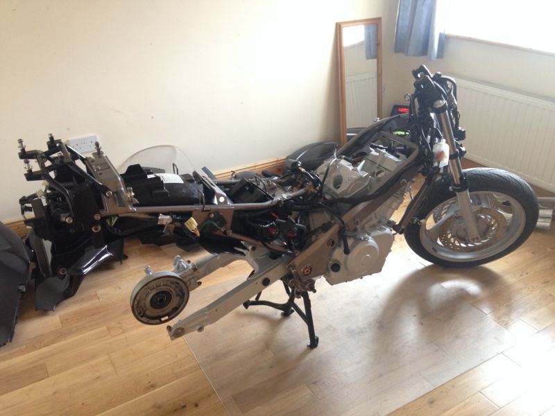
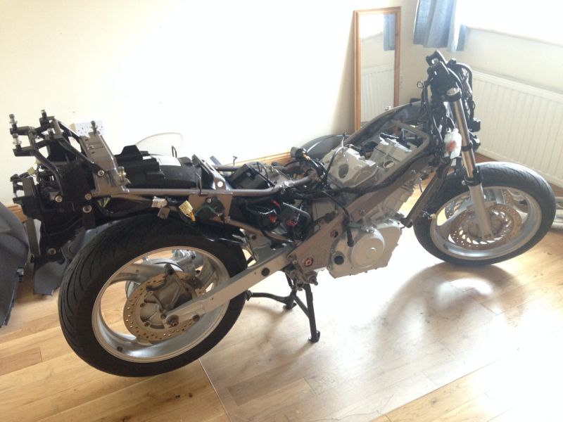
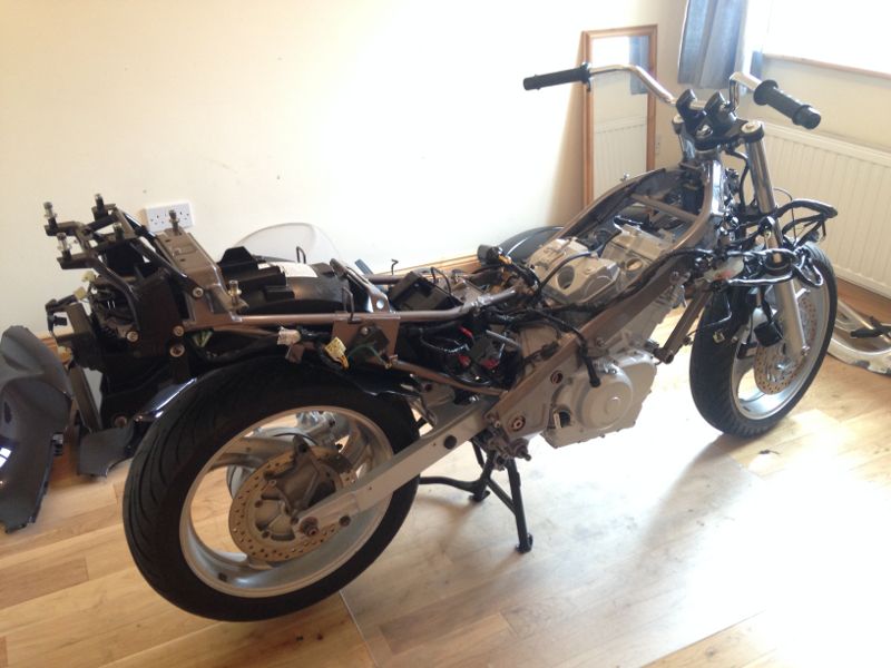
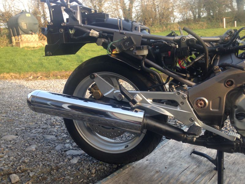
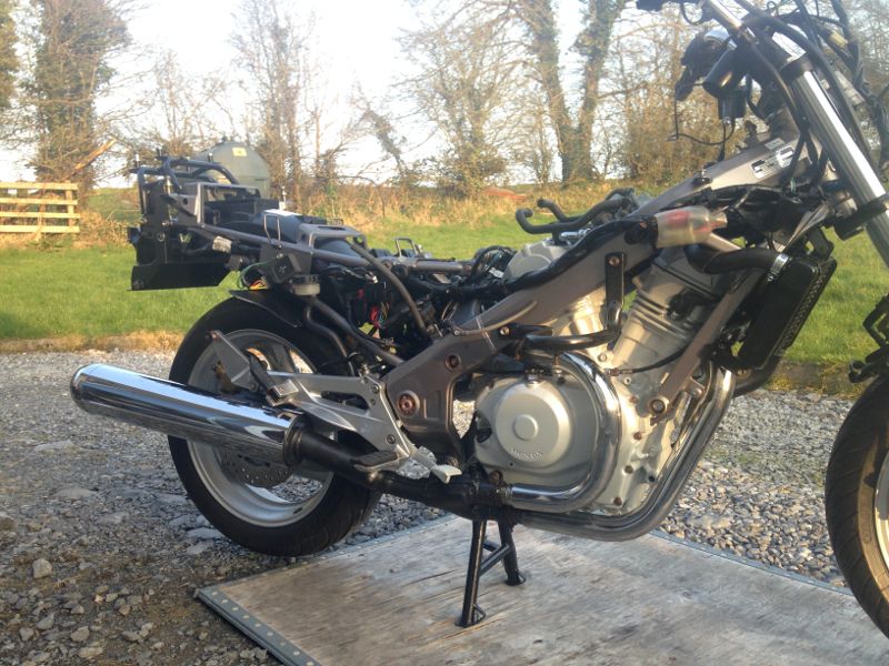
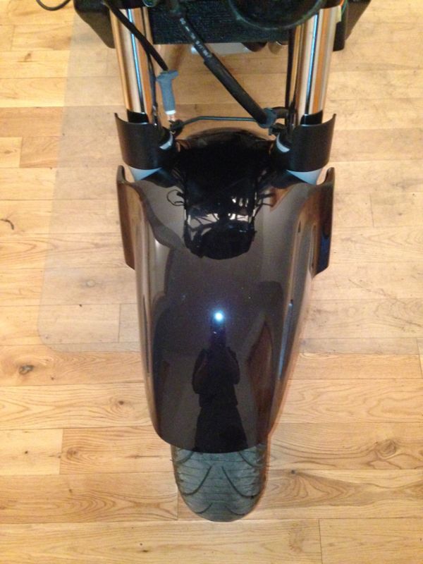
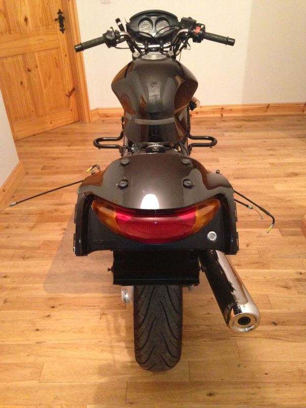
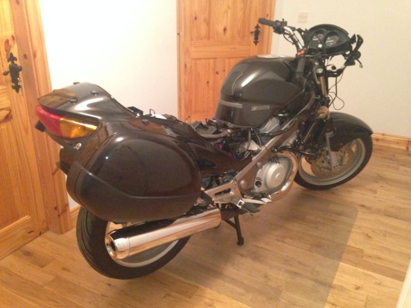
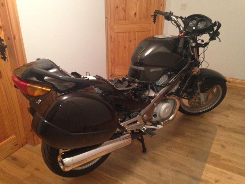
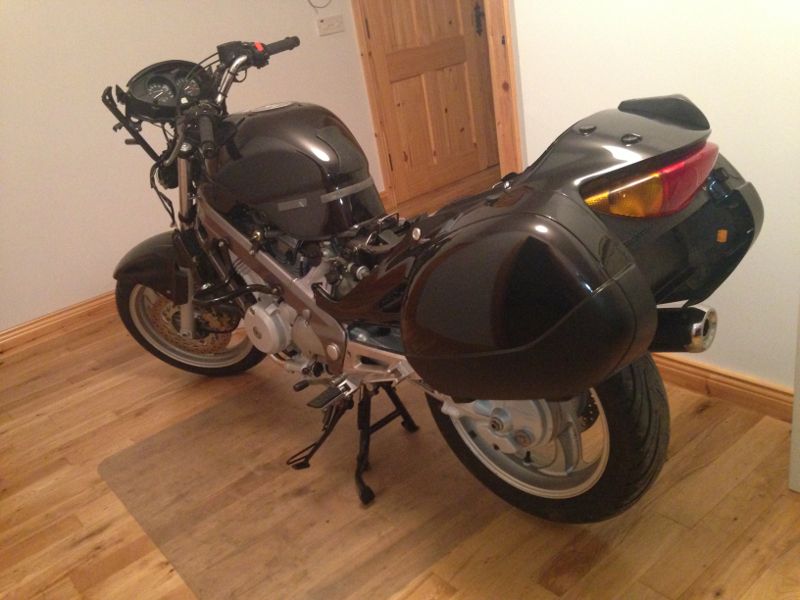
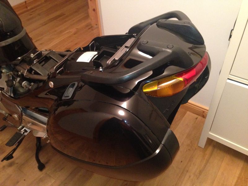
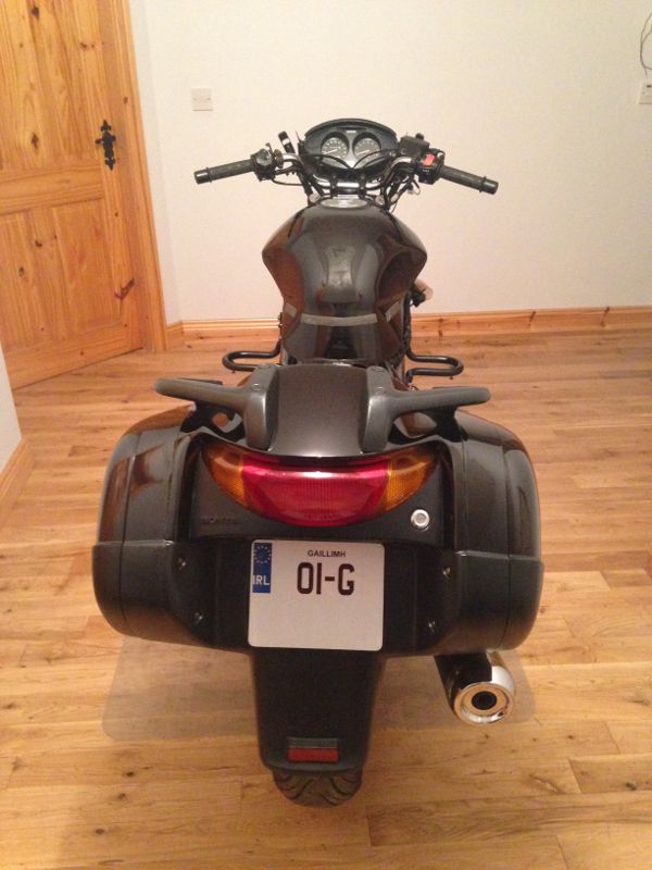
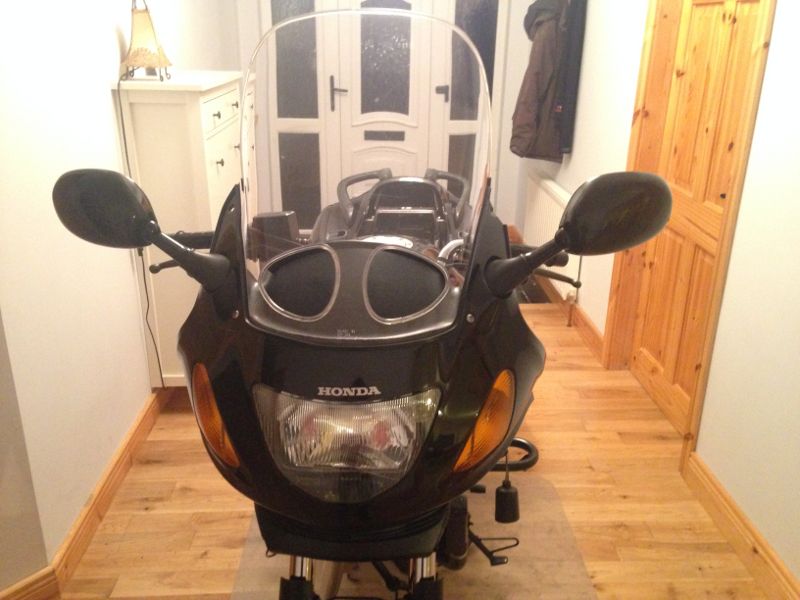
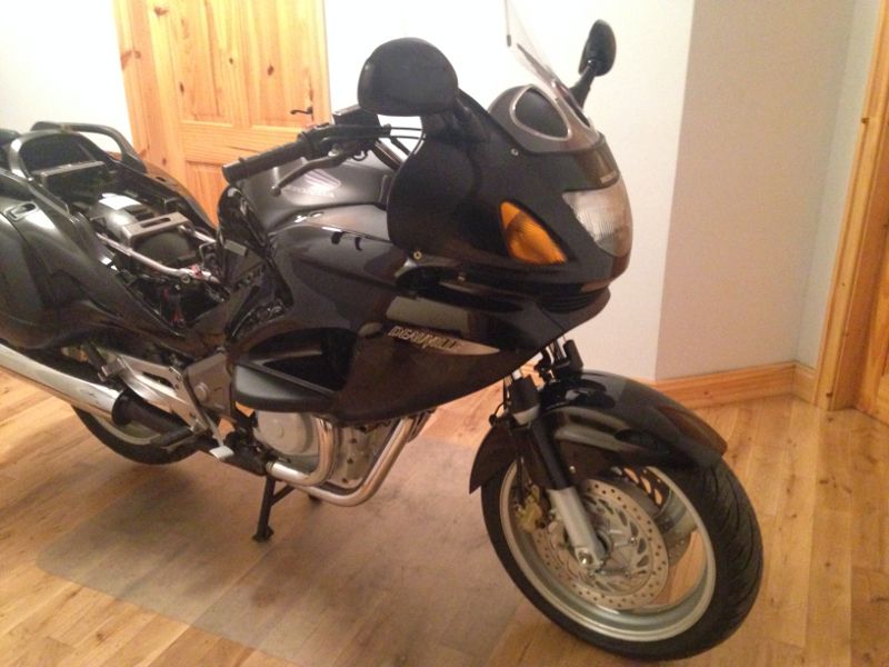
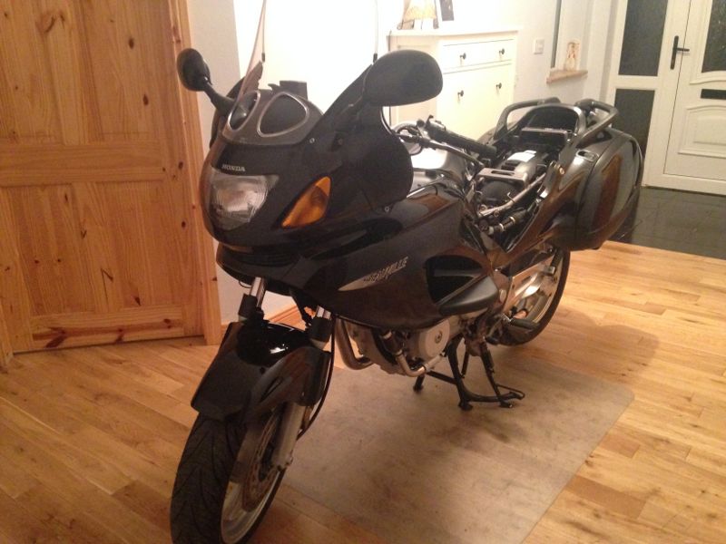
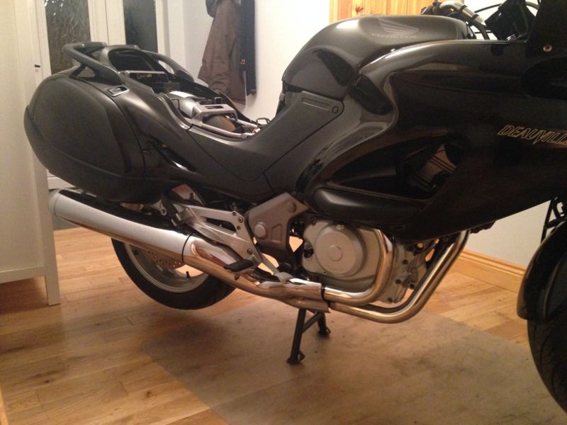
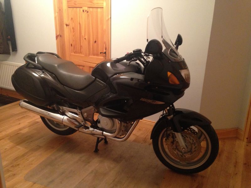
Here are the "before" photos:
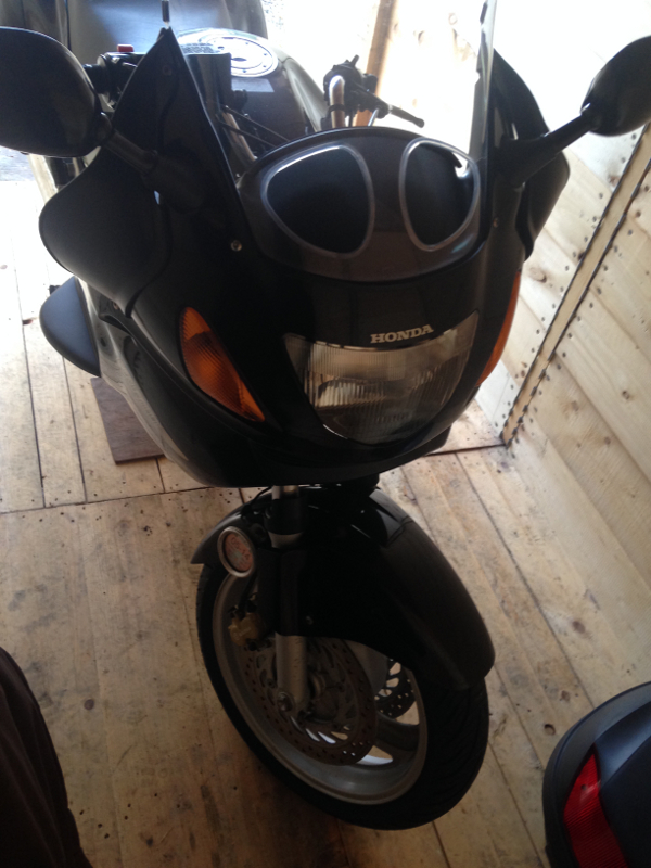
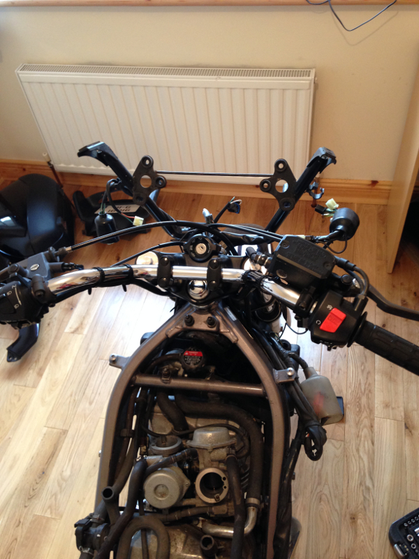
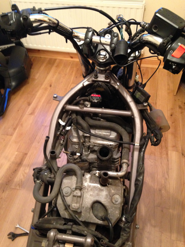
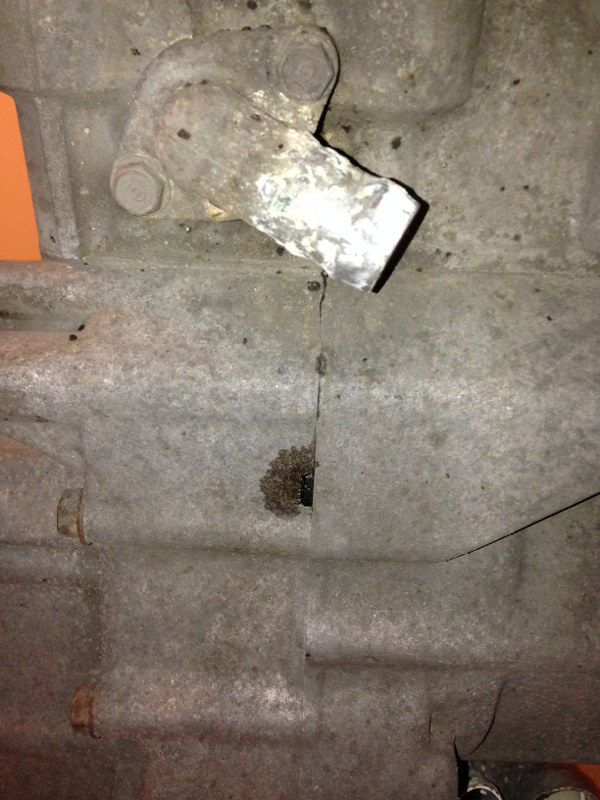
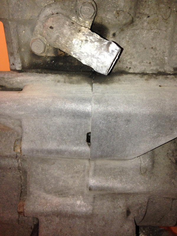
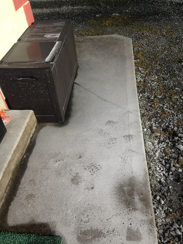
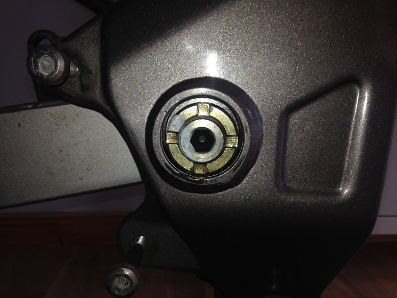
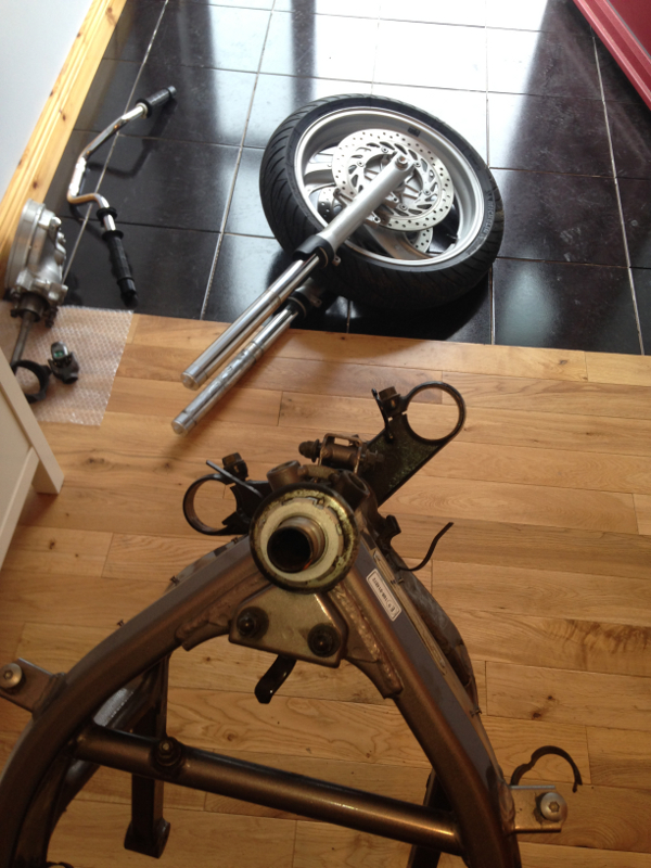
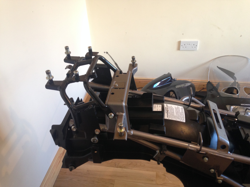
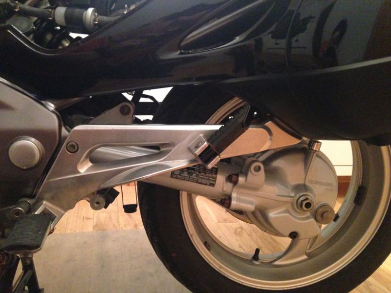
I got the front fairings off easily enough because I had them off during the summer when I balanced the carburettors. I had to consult my workshop manual when I was removing the plastic bits surrounding and including the panniers because they seemed to be stuck. I thought I'd missed a clip or bolt, but it turned out that the rubber bushing was stuck solid to the metal stub that it sat on. A bit of careful elbow grease got it off. The metal stub is the one in the centre of the photo below.
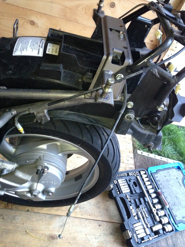
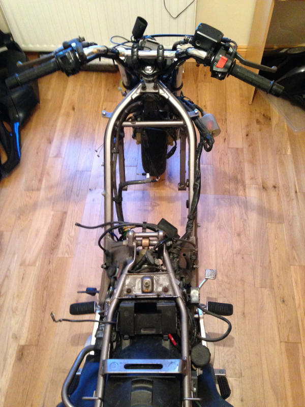
This is the only "during" photo that I have that's worth posting, because the rest are all close-ups of screws etc to remind me what goes where when I'm putting it all back together.
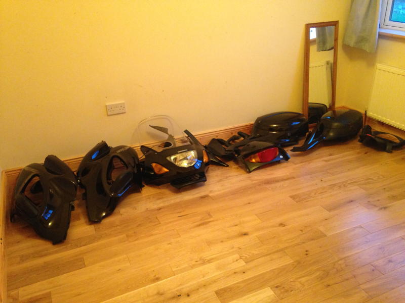
All the plastic bits safely laid out where they won't get scratched:
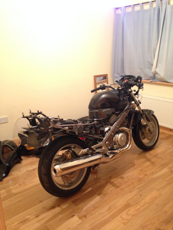
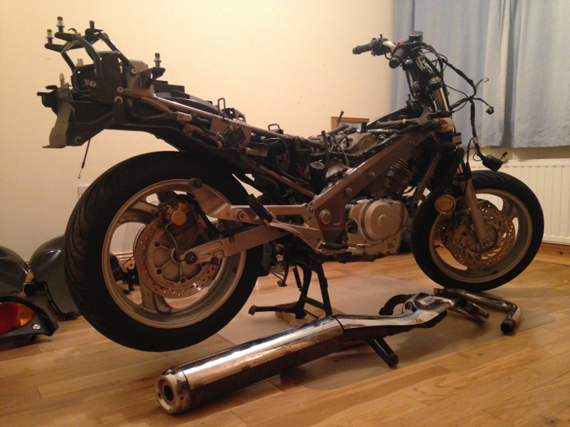
With all the plastic removed from the bike, I pulled it out of the shed. I couldn't believe how much lighter the bike is without the fairings. I was expecting it to be lighter, but I was amazed at how much of a difference there was. I couldn't resist taking it for a short spin down the road. How often am I going to get a chance to ride it when it's completely naked? :)
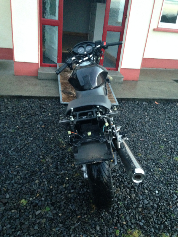
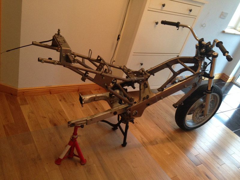
Ready to go inside:
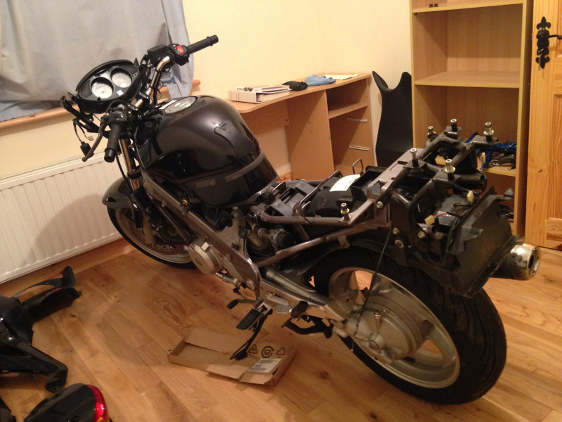
Inside, ready for the real work to begin:
That's as far as I've gotten because I was busy (visiting, eating cake etc) over the Christmas. I'm hoping to get stuck into the real work over the next few weeks because I want the bike ready for the road as soon as the weather starts to improve. I'll update this thread as I progress with the job.
29 January 2014
Back By Popular Demand!
I was given a bit of grief at the weekend by a few members, not mentioning any names, (Phew...cough...Nigel The Plumber...cough :P ) for not progressing any further with my overhaul.
I had a few hours free yesterday evening, so I'm updating the thread with the work I've done since.
Day 2
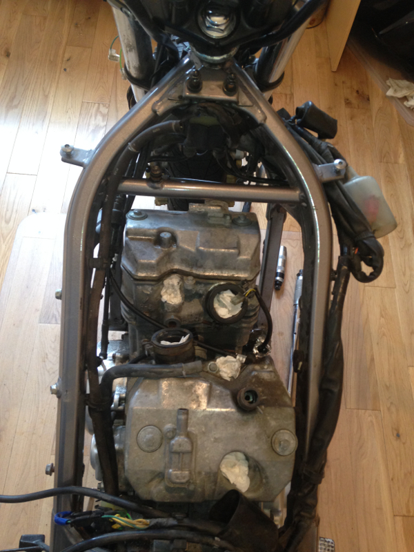
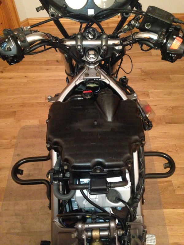
I'm working towards removing the engine from the frame, so I started by removing the petrol tank and battery:
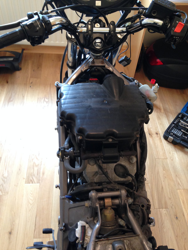
Then removed the air filter and air filter housing:
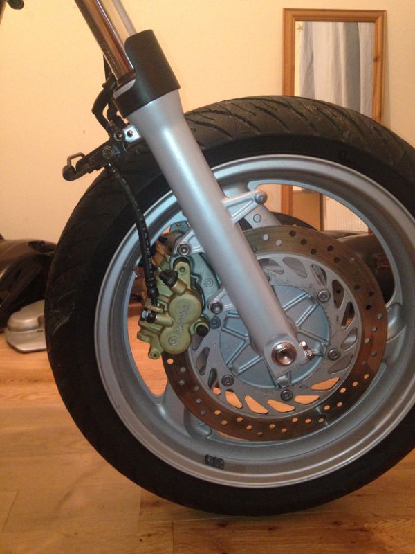
Removing the instrument cluster isn't necessary to get the engine out, but it was sticking out of the bike up there on its own, so it looked like the next thing that should come off. I also removed the speedometer cable from the front hub because it was just hanging off the bike after removing the speedometer.
Next off was the horn, then the bracket that holds the instrument cluster and headlight, as well as detaching any wiring that was tied to it:
Front mud guard was next:
Then the gear pedal and linkage and the left-rear engine cover:
Then I drained the engine oil. As I couldn't run the engine, to warm the oil, with all the bits missing from the bike, I decided to put the bike on the side stand and leave it draining overnight.
Hopefully that will keep my subscribers at bay for another while until I get another few spare hours to do some more work. :P
02 February 2014
I spent a bit of time working on the bike this week when I had time.
Day 3:
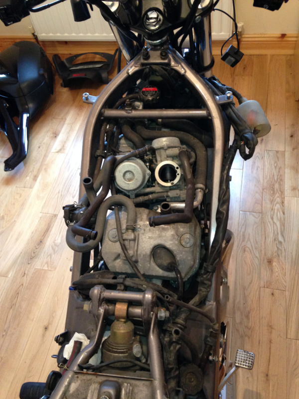
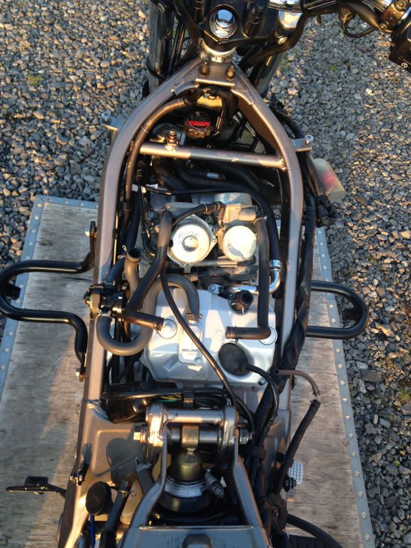
Next in line to be removed was the carburettors. That involved removing throttle and choke cables, fuel pipe and secondary air system hoses:
Then I removed the exhaust. It took a lot of WD40 to get the downpipe clamp off the front downpipe, then a lot of wiggling to get the muffler off the downpipes.
Day 4
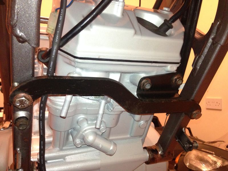
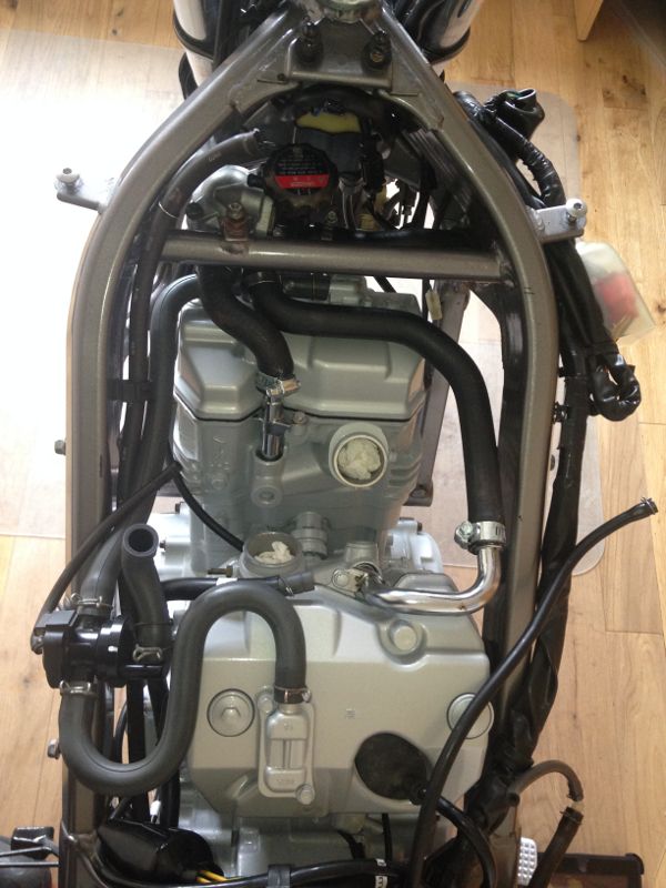
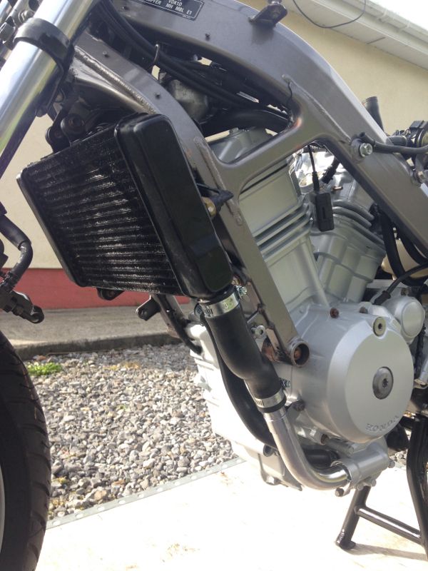
Friday evening I removed the radiator and it's hoses and the heat shield behind it:
I then removed the secondary air system, the coolant hoses and filler, and detached a lot of the wiring from the engine:
Day 5
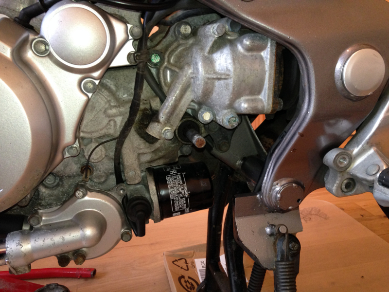
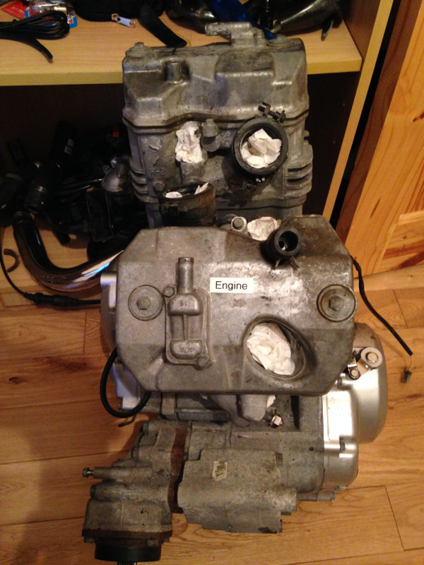
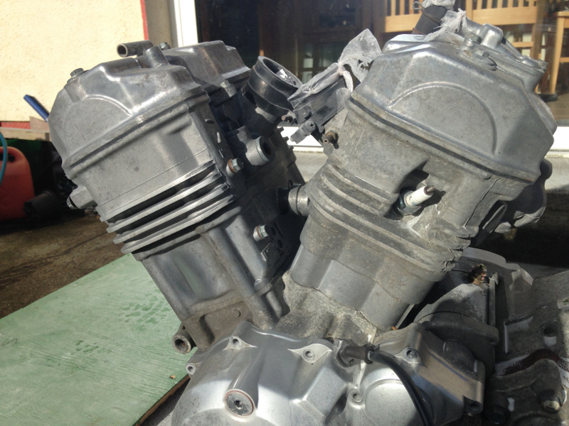
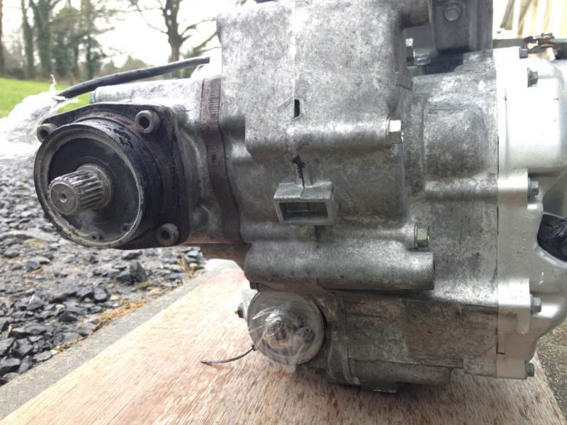
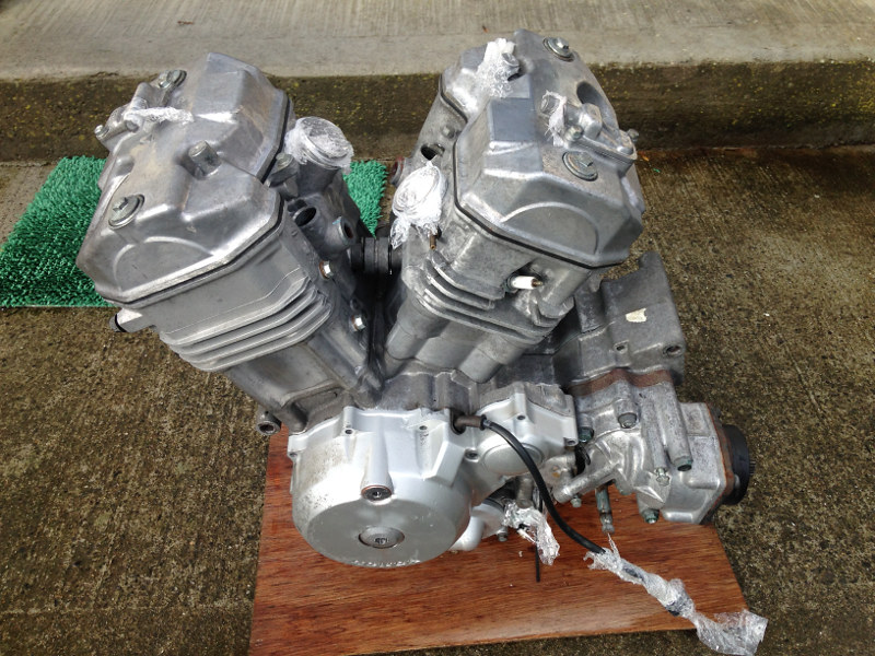
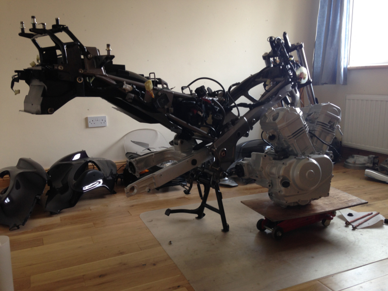
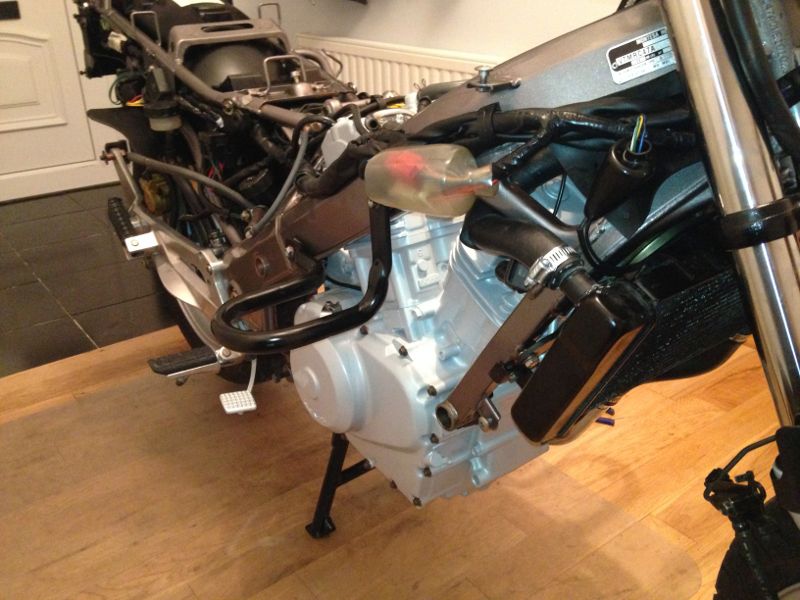
I spent all day Saturday trying to remove the front engine mount bolt. I got the nut off the end easily enough, but the bolt was stuck inside in the engine casing. I tried tapping it out with a hammer. I tried using an impact driver to twist it. I tried hitting it harder with a hammer. I tried twisting it with a long breaker bar. I tried a bigger hammer. Then I gave up because I could feel the bolt starting to shear when I put I lot of pressure on it. I was also afraid I'd crack the engine casing as it's only aluminium. I had been afraid of using heat, because I was afraid of melting the aluminium, but after talking to a friend who's a fitter (as well as anyone else who'd listen to me complaining about it), I decided to use a small, hand-held gas soldering torch to heat the front of the engine because he assured me I wouldn't be able to reach the melting temperature of aluminium with that torch. I had also asked a member of http://www.deauvilleuk.org/ because he strips Deauvilles for parts, so I figured he'd have come across the problem before, and he gave me the same advice. I didn't get around to this until this morning, but after an hour of heating, hammering and turning with a socket, the bolt finally started to move. Once it started to move, I spent another hour turning it back and forth until I could turn it a full revolution, and then hammered it out with a long punch. It doesn't look like a lot of progress, but getting that bolt out took a lot of work. I had to sit down and rest for a while before I had the energy to tackle removing the engine from the frame. Removing the engine from the frame was awkward and should ideally be done by two people. I'll get help when I'm re-fitting it. I had a trolley jack under the engine, supporting it, so I couldn't lower the engine enough to get it out under the frame. I ended up letting the engine gently tip forward off the jack, onto the floor, so the cylinders were clear of the frame. I was then able to slide the engine out from under the bike. I took plenty of photos of the engine being out because I was so happy to finally have it out:
I've been carefully labeling the parts as I removed them from the bike, so that I would know what it was when I was rebuilding the bike. Here's an example: :D
Now the real work can begin.
04 March 2014
So, it's time to update this thread. I've been too busy working on the bike to write about it.
Day 6
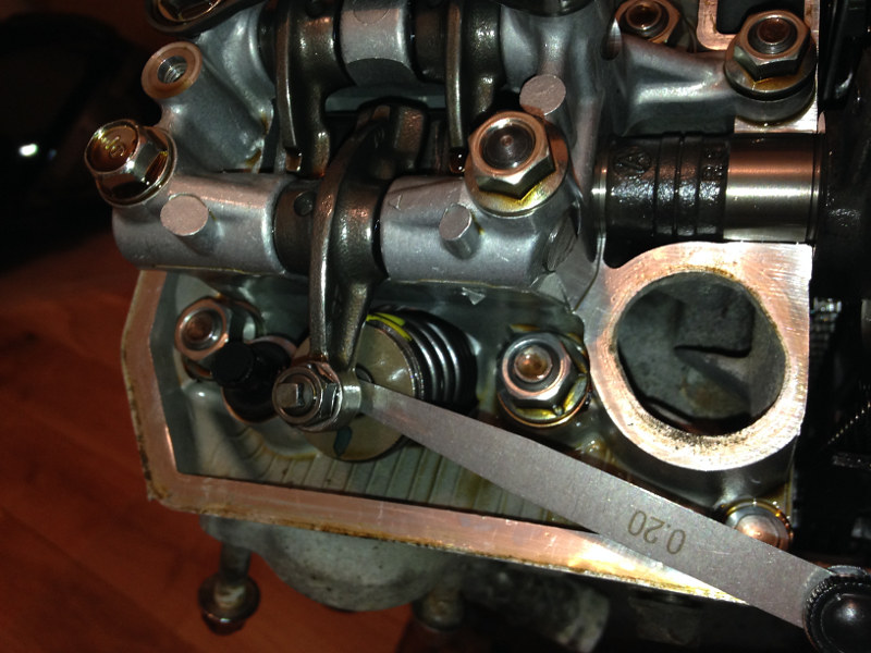
Day 6 was just a short job, one evening after work. I adjusted the valve clearances. With the engine out of the bike, it was a very simple job. I just had to remove the two bolts holding on each valve cover, then using a socket on the flywheel bolt, turn the crank shaft until the cylinder I was working on was at Top Dead Centre. The valve clearances were tighter than specified. I was confused at first as to how they could get tighter with wear and tear, until I read somewhere that the reason is that the valve seats wear more, causing the clearances to close.
Checking the valve clearances:
Day 7
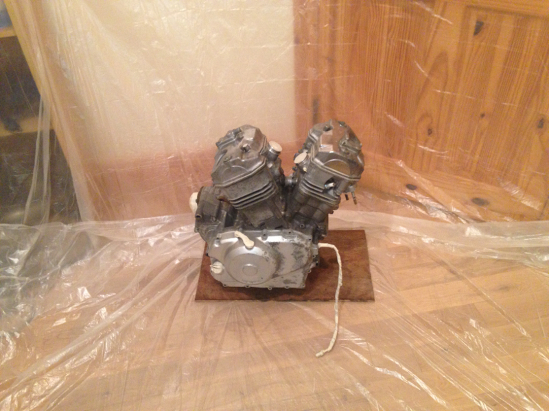
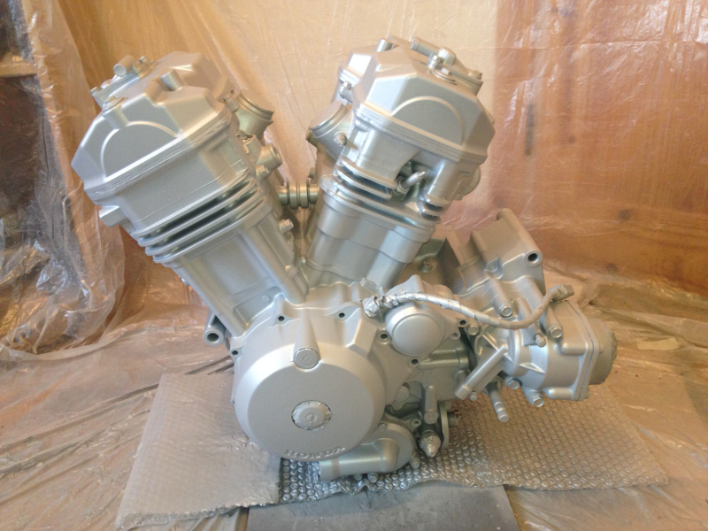
My next task was to start cleaning the engine in preparation for painting. After plugging all the holes and wrapping the wires in cellophane shrink wrap (industrial cling film) I degreased it by applying Gunk degreaser with a paint brush. From what I can tell, Gunk is simply kerosene in a fancy tin, sold for about €8 per litre.
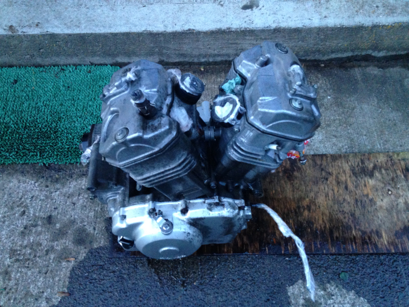
After allowing the Gunk to do it's thing for about ten minutes, I hosed it off. I then sprayed a mixture of snow-foam and car shampoo on the engine to wash off the Gunk, and after allowing it to dwell for a few minutes, hosed it off again.
With the engine washed clean, I wanted to remove the white, powdery aluminum oxide from the surface. I did a lot of research on the best way to do that. Some people suggested brake cleaner and a wire brush. Here are the before and after photos of my test patch for that method:
Before:
After:
As you can see, it was working, but from the amount of brake cleaner and elbow grease to clean that small area, it wasn't viable to clean the whole engine that way. I was wary of using any chemical cleaners because many people had reported problems, such as pitting of the surface, or black spots caused by impurities in the aluminium being drawn to the surface. Bead blasting is supposed to bring the aluminium up to it's original shine, but leaves a dimpled surface from where the beads impact it. Soda blasting seemed to be the safest method overall. The disadvantage of soda blasting is that a whole engine can't be done and I didn't want to strip the engine down. So after about a week of researching online, I came up with a homebrew soda blasting solution that worked perfectly.
Day 8
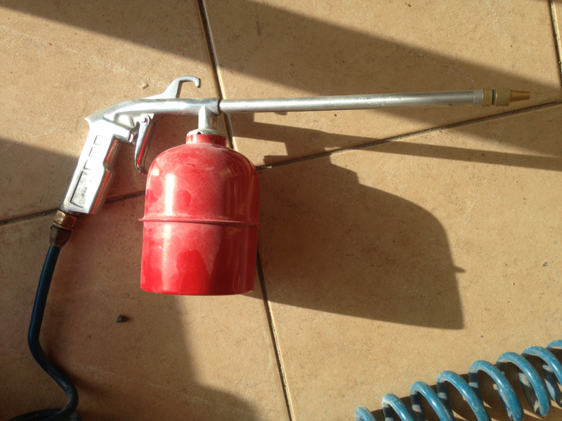
Compressor paraffin/wash gun:
Six kilograms of baking soda:
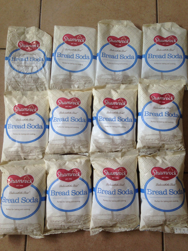
<EDIT>: I only used 3.5kg of the baking soda, and I wasn't trying to spare it. Sodium bicarbonate can be bought in agricultural shops for treating cattle with upset stomachs. A 25kg bag is about €20, but it worked out cheaper to buy food-grade baking soda because I was only going to be using a small quantity. I also found that some places sell it in paper bags, so the soda is damp and clumpy, so won't work for this job. <\EDIT>
The baking soda particles are much smaller than those normally used for soda blasting, and I assume they use a higher pressure (I had the compressor set to about 100psi [~7 bar]), so it's not as aggressive as regular soda blasting. It was then safe enough to use this on the whole engine. The soda was aggressive enough to remove the corrosion from the engine, without doing any damage. The main disadvantage of this method is that the soda goes EVERYWHERE!
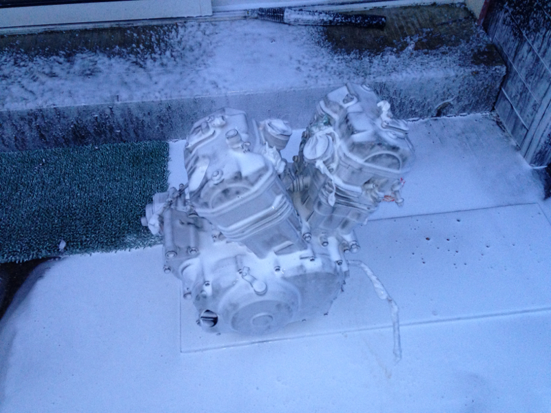
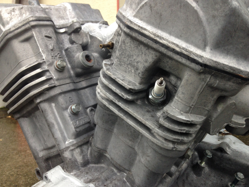
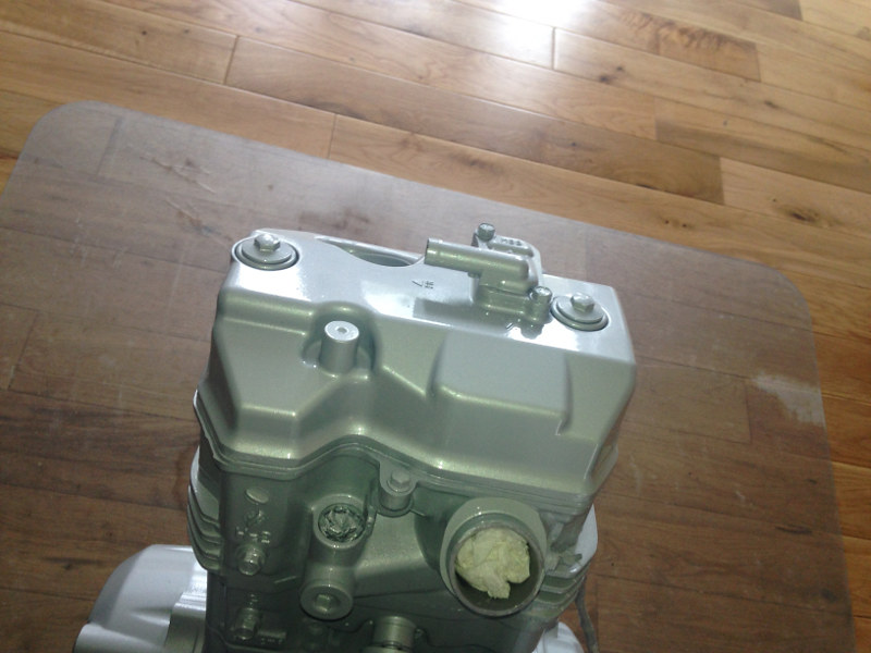
Use of a good quality dust mask and goggles is essential for this. I'd also recommend moving vehicles, or anything else you don't want covered in baking soda, out of the area. The baking soda is water soluble, so it washes away after a day or two of rain though. To give an idea of how well it worked, here's a photo of the difference between the front cylinder, which I'd cleaned, and the rear cylinder which I hadn't:
Day 9
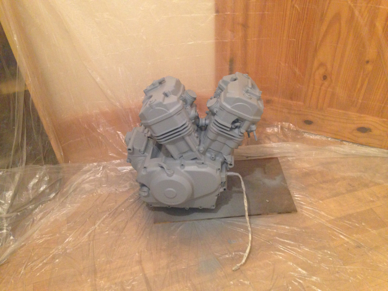
The soda blasting job ran into day 9 because I foolishly forgot to use a moisture trap on the compressor when I was soda blasting, so after a while the soda started to clog in the gun. I was able to continue working for a while by tapping the nozzle of the gun with a heavy bolt, to keep the soda flowing but after a while the soda was just too damp, so I gave up for the night. Below are photos of the engine after I finished soda blasting it on day 9 and then threw loads of jugs of warm water over it to wash away any soda left on it.
04 March 2014
Day 10
Day 10 was one of those days when you spend a lot of time working on something, but when you look back, the results aren't really visible. I removed the front brakes; calipers, master cylinder and lever as a complete system, without opening it.
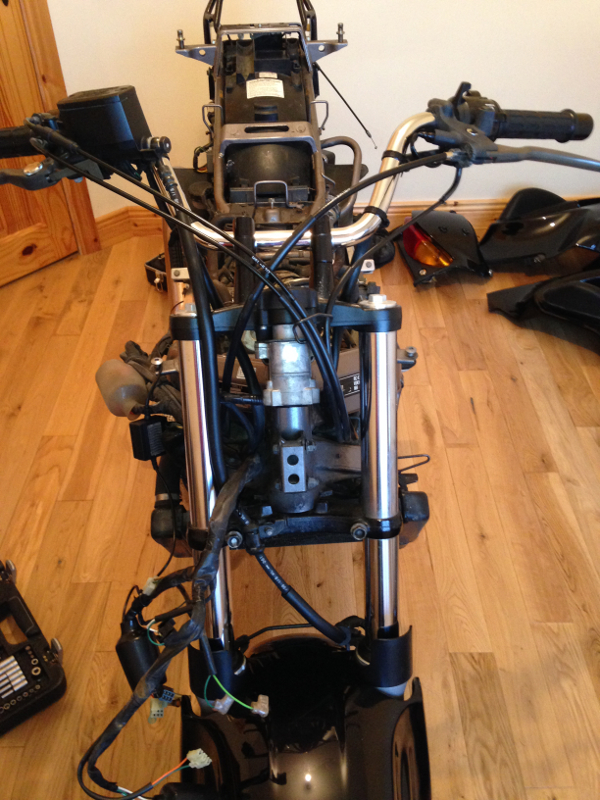
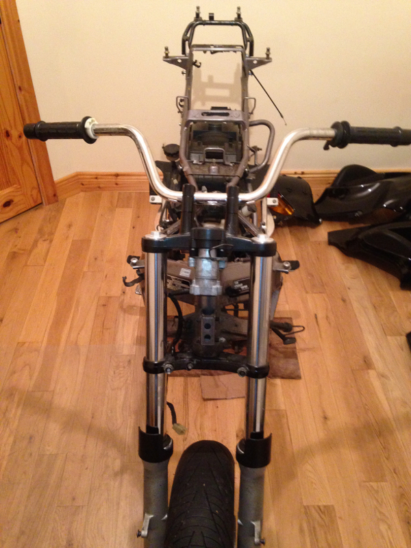
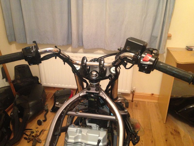
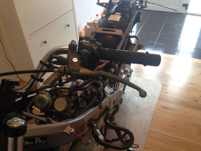
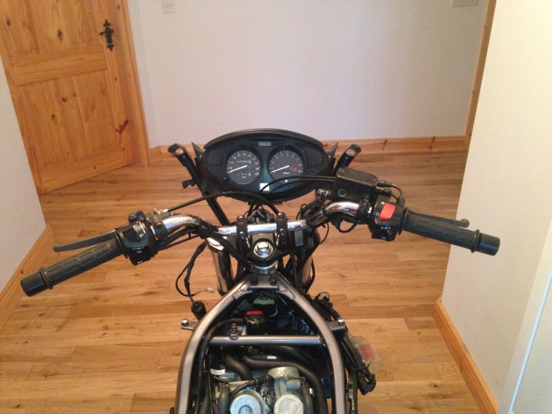
I then stripped the whole wiring loom from the bike, including the ignition control unit, fuel pump, ignition coils, relays, and handlebar switches. The only real visual evidence of that was the bare handlebars:
Day 11
The next day was a short one, but I don't remember why. I only removed the rear cowl bracket and the right-hand footrest bracket. I've a vague recollection of getting interrupted by a phone call.
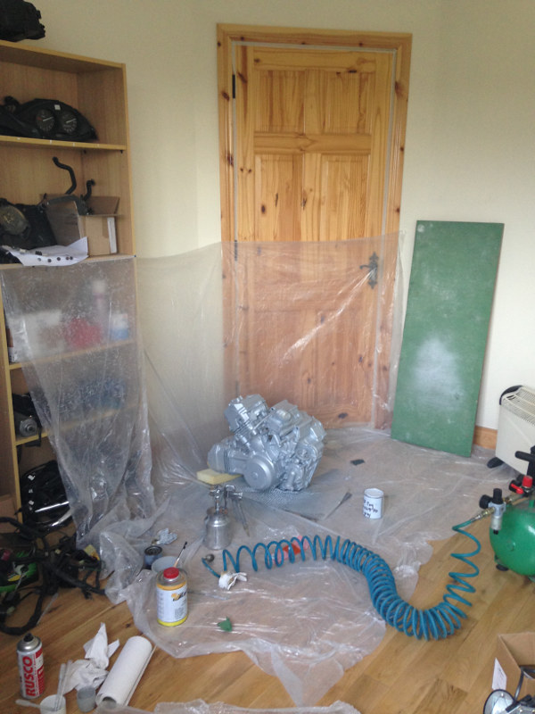
Day 12
My original plan was to paint the engine outside in the bike shed, but I was afraid that the cold, damp weather would affect the finish, even if I heated the shed, so I decided that the best place to spray it was inside. To make sure I didn't pollute the whole house with thinner fumes, I taped up the door, including the keyhole and hung plastic sheeting up in the room where I was working, to protect the walls and door from overspray. I then had to climb in and out the window if I wanted to get anything. :D
I masked off anything on the engine that I didn't want to spray:
The paint won't adhere to aluminium properly unless it's correctly primed, so the first coat was etch primer from an aerosol can:
I got the silver paint matched up to a plastic panel off the left rear of the engine. B&C Paints in Galway have just installed a spectrophotometer to remove the guesswork from matching paint. Just give them something and the spectrophotometer will pick the correct colour. I started with an airbrush and sprayed into all the nooks and crannies of the engine and anywhere else that may not get covered properly with the spray gun.
Day 13
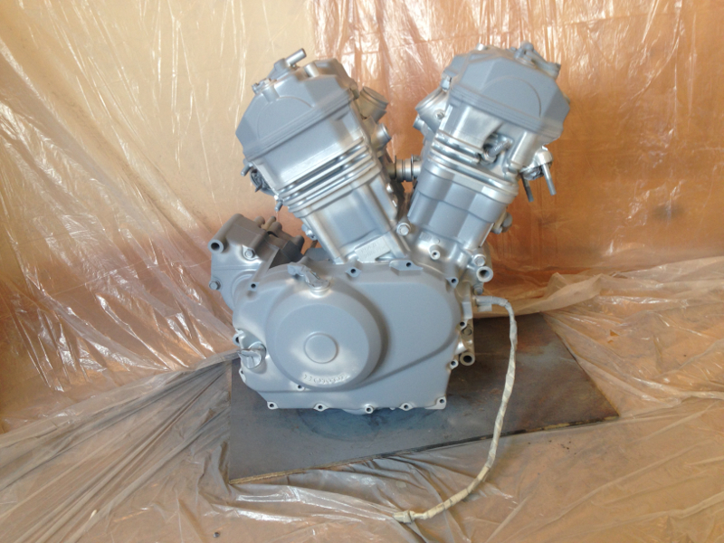
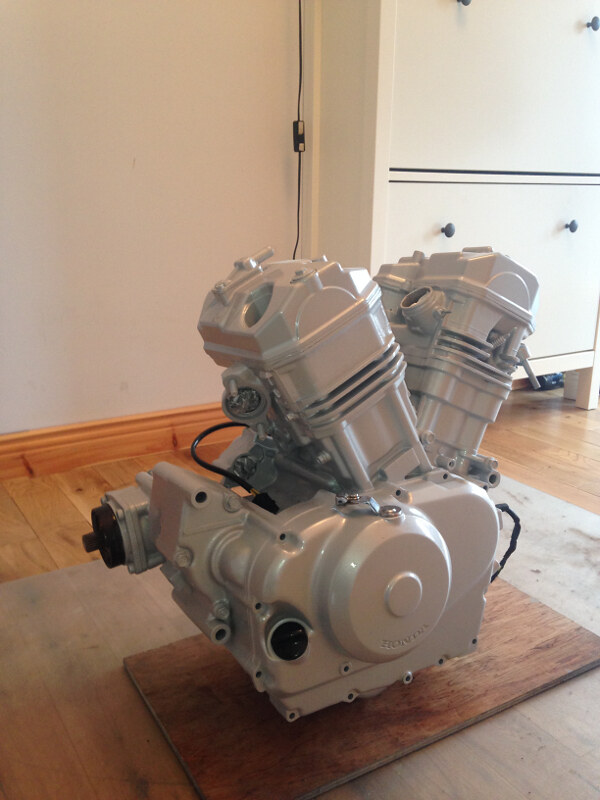
The next day, I sprayed the rest of the engine.
Spare bedroom/Spray booth: :D
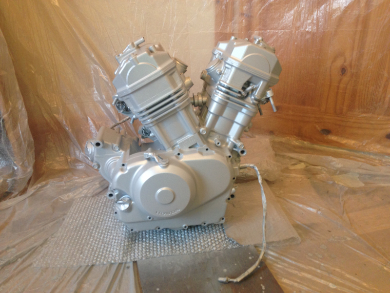
Engine after spraying with the base coat:
04 March 2014
Day 14
I wanted to give the base coat a day or two to harden before applying the lacquer, so I continued to strip the bike down after I sprayed the engine.
The next thing to be removed was the rear brakes. As with the front brakes, I removed the whole lot without disassembling the system.
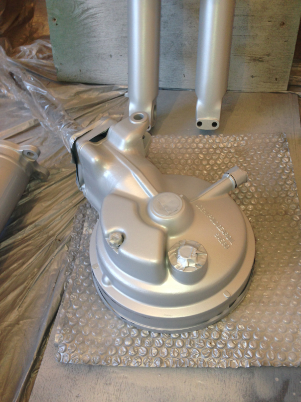
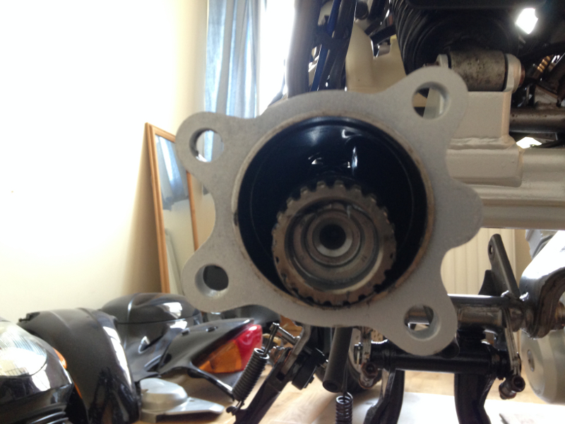
Next off was the final drive hub:
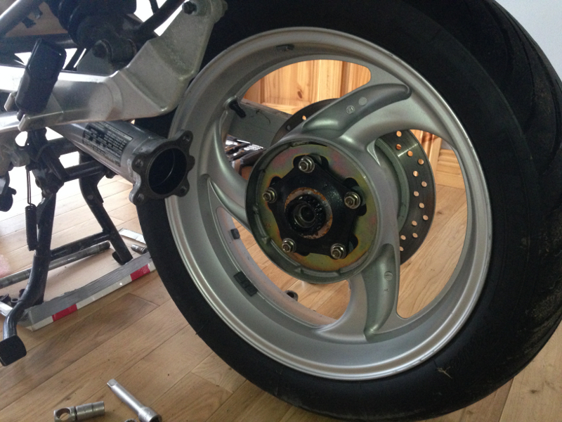
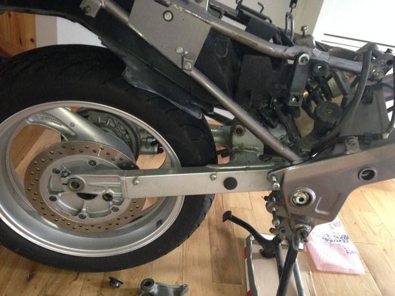
Back wheel came off next:
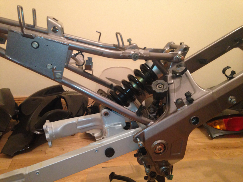
And finally the rear shock absorber:
Day 15
To remove the swing arm, a special tool is needed to remove the lock nut on the right-hand pivot bolt:
The special tool is available from David Silver Spares for over €55 and needs to be ordered in especially. :o
However, after some careful measuring, buying a spare 24mm impact socket and spending some time with an angle grinder, I was able to make one myself (the socket cost about €8).
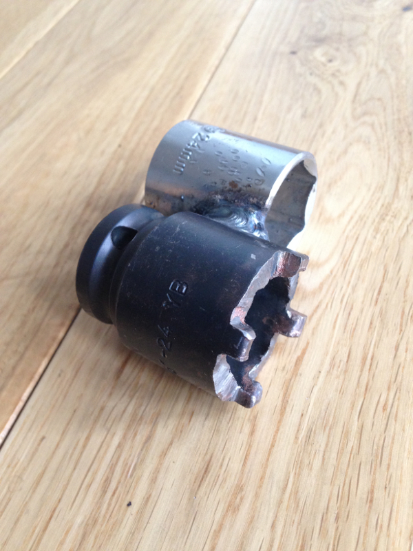
I was originally just using the socket on its own. I had to weld the second socket onto it afterwards to counter hold the pivot bolt with an Allen key, while turning the lock nut. The lock nut was so tight that I could not budge it. I finally got fed up of trying, and decided to continue stripping down the rest of the bike while the WD40 was soaking into the lock nut. The lock nut wasn't seized or corroded in any way, it was just REALLY tight.
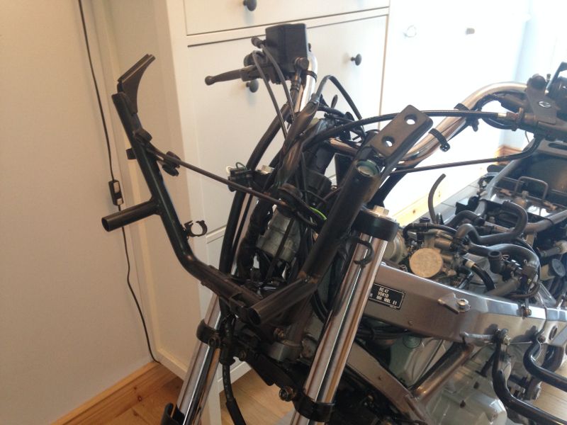
I removed the handlebars:
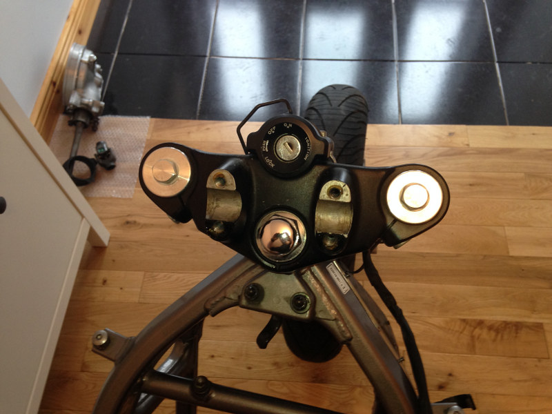
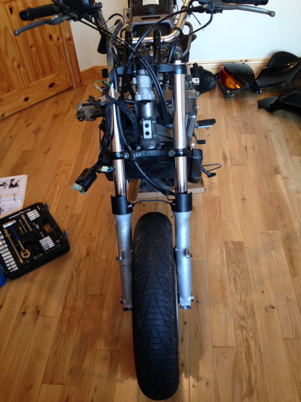
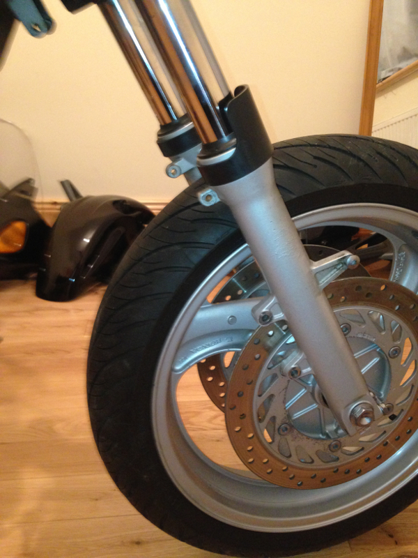
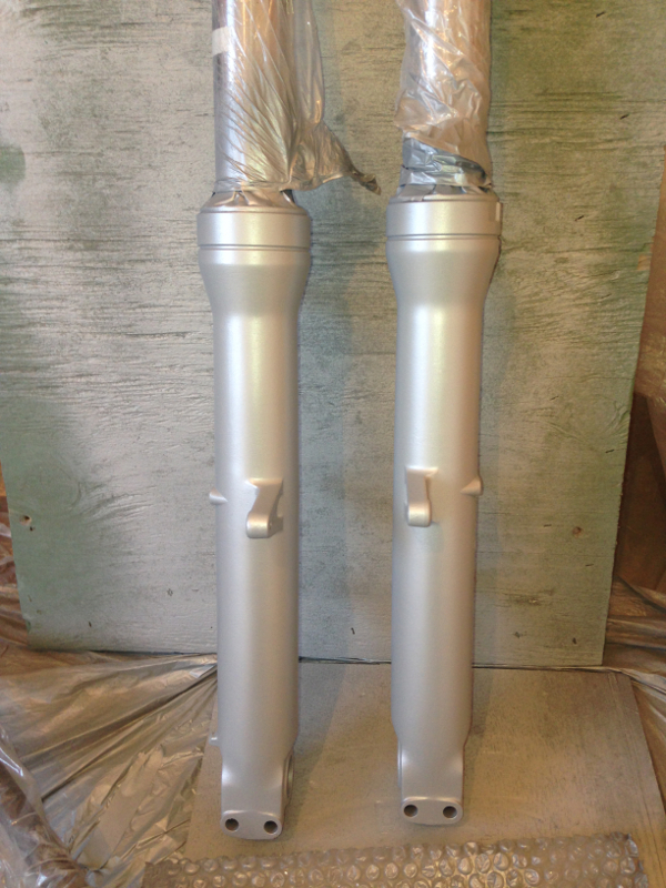
Then the front wheel and forks:
Then the steering stem:
Finally, I removed the centre stand and side stand:
Day 16
I'm going to call this Day 16, even though it took me three days of hard labour to get to this point. I tried everything to remove the swing arm lock nut. I tried a breaker bar. I tried a longer breaker bar. I tried hammering the breaker bar with a lump hammer. I tried using an impact driver and hammered it with a lump hammer until my arm hurt from the effort. I put an extension bar on the socket, then supported the extension bar with a block of wood, so that I could jump on the end of the breaker bar. Nothing worked. It didn't even budge.
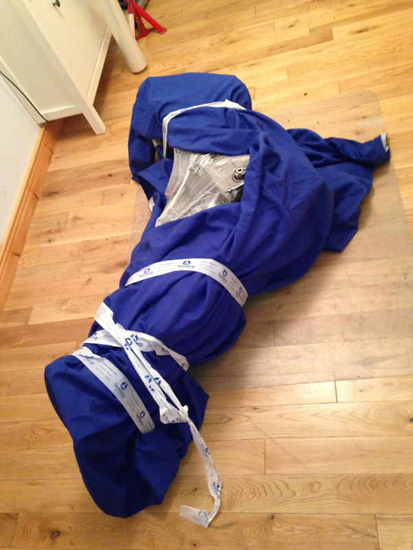
Finally, on the third day I wrapped the frame up to protect it and took it to a garage in Mountbellew. They work on trucks etc, so I knew their air impact wrench would be a powerful one. They very obligingly allowed me to use it. I gave it full power for about ten seconds and it never budged. The guys in the garage were staring with their mouths open, because they'd never seen it fail to remove a bolt. I gave the compressor a while to recover while I chatted with the guys in the garage. Then I gave it another go, nothing happened for about four seconds, and then the whole pivot bolt spun off. I gave a shout with delight and felt like jumping around the garage.
The lads in the garage looked slightly amused by my excitement at getting a bolt off something. :D
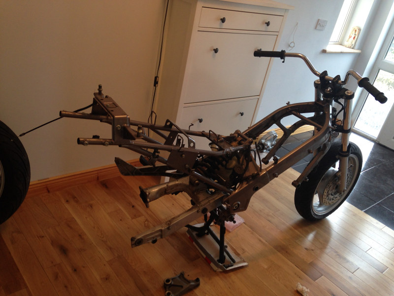
You can see the pivot bolt and lock nut sitting proud of the frame just before I unwrapped the frame to continue working on it:
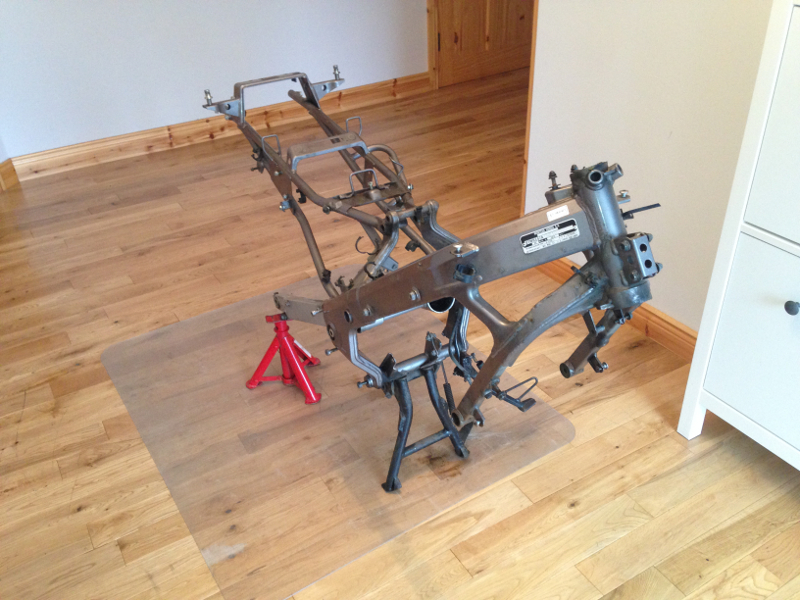
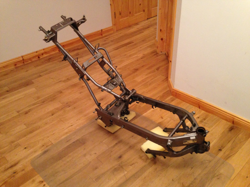
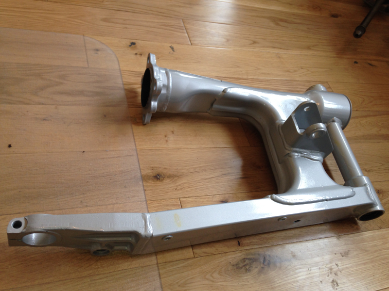
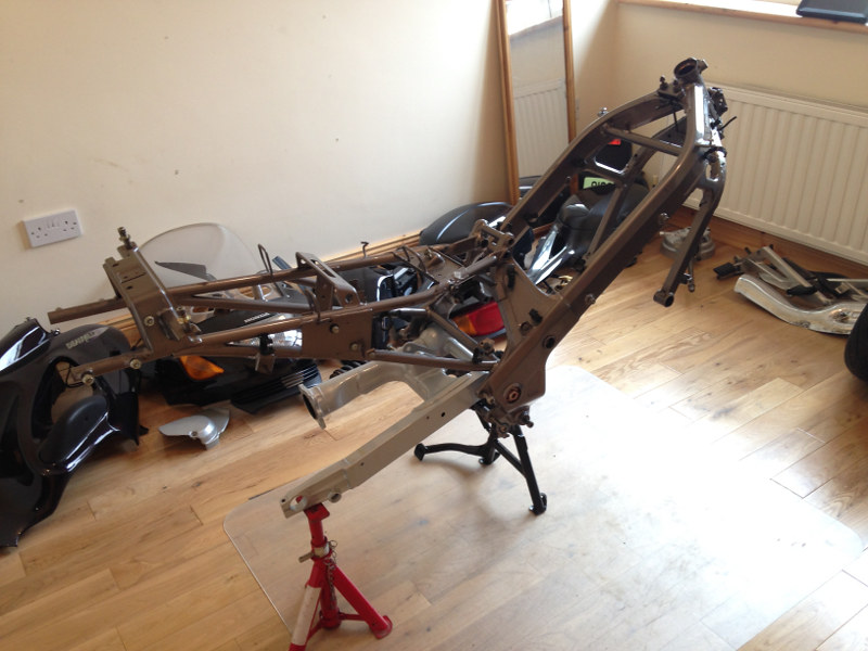
And finally, after removing the swing arm, I had the bike stripped down to just the frame:
08 March 2014
Ok, so time to update the thread again (and get it back on track before a fight breaks out )
Day 17
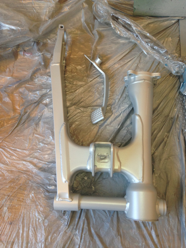
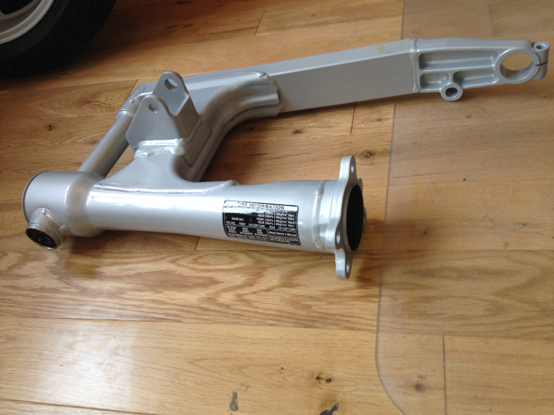
The Deauville has three colours on it. The fairings, which are your chosen color, (black in this case); the frame, which is a dark silver/grey; and the engine, swingarm, final drive hub, front forks and brake pedal, which are a bright silver colour. I realised after I painted the engine, that the other bright silver parts would look shabby in comparison to the freshly painted engine, so there was only one solution.
I lightly sanded the parts (swing arm, final drive hub and forks) to remove any loose paint or corrosion, masked everything up and then sprayed them with etch primer:
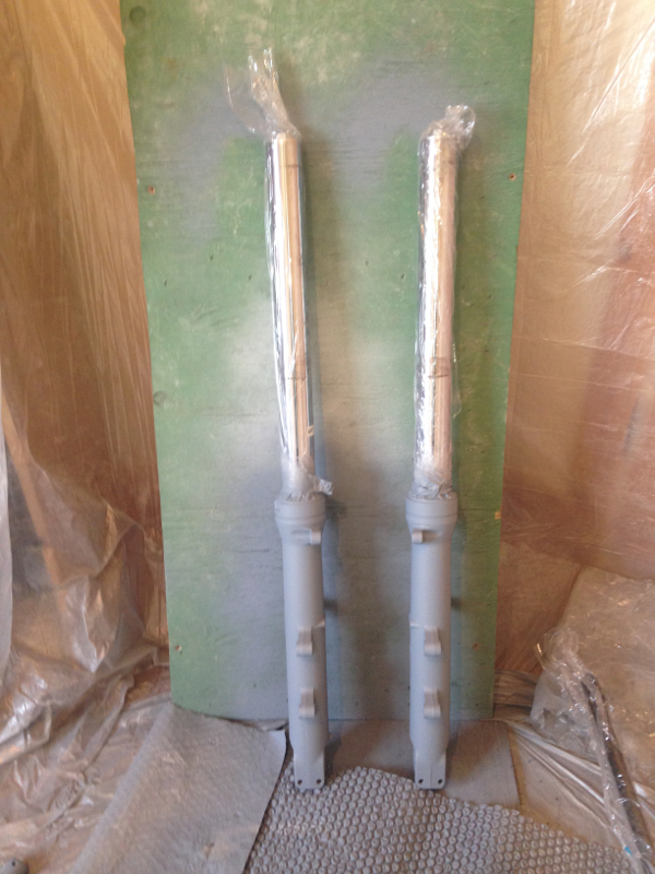
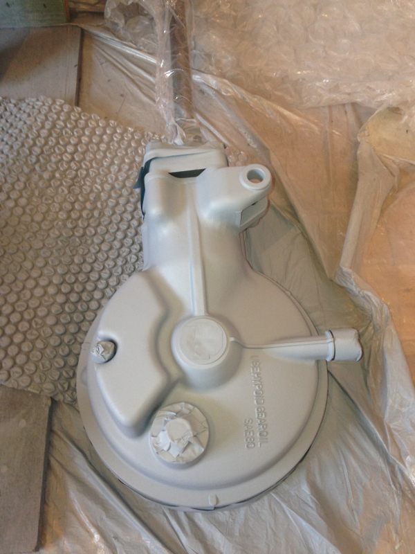
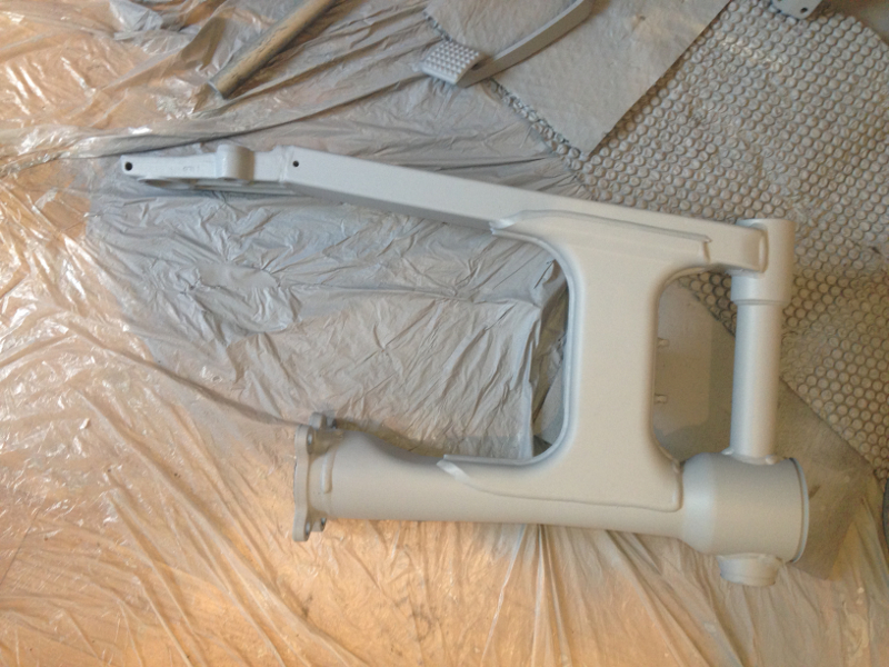
Then I sprayed them the same colour as the engine:
Day 18
When I was researching the best way to clean aluminium, I also researched the best way to protect an aluminium engine because I had been thinking about polishing the engine to a shine. However, most of the engine is made from sand cast aluminium and I read somewhere that you should not polish a cast aluminium engine to a shine because it reduces the cooling of the engine (due to a reduced surface area, I presume). While I was looking for ways to protect polished aluminium, I came across details of a company called POR-15 that make very hard-wearing paints and coatings. One of them is Glisten PC, a clear coat that it supposed to be so durable that they've painted it onto a metal bar, bent the bar and hammered it flat, and the paint still didn't crack. I figured this would be perfect for protecting the front of my engine from stone chips, so I went about looking for some. I contacted Larry from www.cleancar.ie, who stocks POR-15 paint. He hadn't heard of Glisten PC, but ordered in a tin of it from his supplier for me.
According to the instructions, they recommend brushing POR-15 paints, rather than spraying. This went against the grain a bit for me, but they say that the paint will "flow out" after it's brushed on, and by the time it has dried, there will be no brush strokes visible. The paint is xylene based so wearing a good respirator is essential, even when brushing it on.
The Glisten PC is a two-part coating, so it must be mixed with hardener. I mixed the paint 4:1 with hardener, according to the instructions and started to paint the engine. It was my first time using Glisten PC, so I decided it would be safer to start on the underside of the engine, where it wouldn't be visible if it didn't work very well. I started brushing it on and the first thing I noticed is that it was very tacky and hard to spread. It reminded me of rubbing a paint brush onto paint that was half dry. I had to use heavy brush strokes to spread it because it was so tacky and thick. After a few minutes, I noticed that it seemed the solvent in the Glisten PC was dissolving the silver paint underneath and, because I was using heavy brush strokes, it was smearing the silver paint! The silver paint had been on the engine for a week at this stage, so it wasn't that the paint hadn't fully dried yet. The instructions say that you can thin the paint up to 30% using either their special thinners, or xylene (you can't use standard thinners). Luckily, I'd taken the precaution of getting a bottle of xylene, just in case I needed to thin it. I thinned the paint by about 30% and continued working. The paint was much easier to spread after thinning, but I found it tended run unexpected off the brush, from time to time, when the brush was touched against the surface. I can only guess that it was caused by whatever ingredient is supposed to help the paint flow out as it dries. I could still see brush strokes in the paint I was applying, but various different accounts I'd read online, as well as the instructions, said that the brush strokes flow out as the paint dries, so I was skeptical, but willing to give it a chance.
By the time I had finished painting the whole underside of the engine, and started to work my way onto the side, about an hour had passed. The instructions say the paint will be touch dry in an hour, so I looked back to where I'd started, to see how well it had flowed out...it hadn't.
The colour was blotchy from where it had smeared the base coat, and the surface was lumpy and there were still brush strokes visible. I panicked a bit because I had already started to apply it to the side case of the engine, where it would be visible, and if that coating is as durable as it's supposed to be, sanding it off wasn't going to work. I decided the best way to recover the situation was to grab my spraying gear and start spraying. It was a rushed job because I wanted to get the gear set up and start spraying straight away over the paint I had applied to the side of the engine, so that the sprayed paint would blend with the brushed paint and cover any brush strokes. I also sprayed the swingarm, final drive hub and forks. In the morning, when I checked how it had dried, the swing arm, final drive hub and forks were perfect, but it was noticeable (if you looked for it) where the brushed paint met the sprayed paint on the engine. The instructions say that a second coat must be sprayed after 6-8 hours and not more than 24 hours, or the surface needs to be machined to roughen it for the second coat, so I sprayed a second coat onto it after work that evening, laying it heavily where the brushed paint stopped and gradually reducing the thickness as I worked away from it. I also gave the other parts a second coat. I was quite happy with the results when the second coat dried.
I must say that although brushing it on didn't work for me at all, maybe someone else with a better brushing technique than me could get a good finish on it, I don't know, but a brush-on lacquer that gives a glass-like finish sounded too good to be true to me, and it turned out it wasn't true. Larry from cleancar.ie hasn't used Glisten PC before, but says that the other paints from POR-15 are very durable. If the Glisten PC is as good as it's supposed to be, it will still be well worth the hassle of applying it.
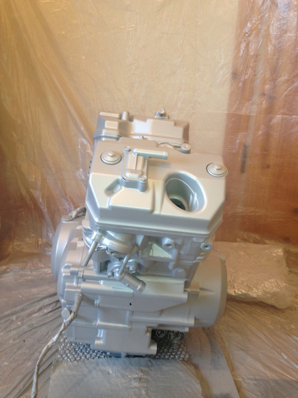
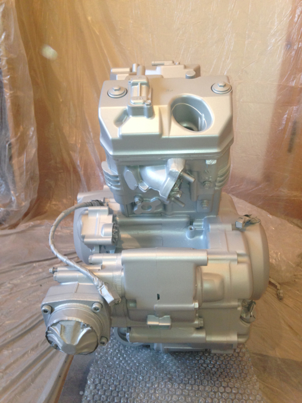
I didn't take any photos after the first coat of lacquer had been applied, because I was fed up, but here are the photos after the second coat:
16 March 2014
I'm about two weeks behind on my write up of my work on the Deauville, so it's time to update it again.
Day 19
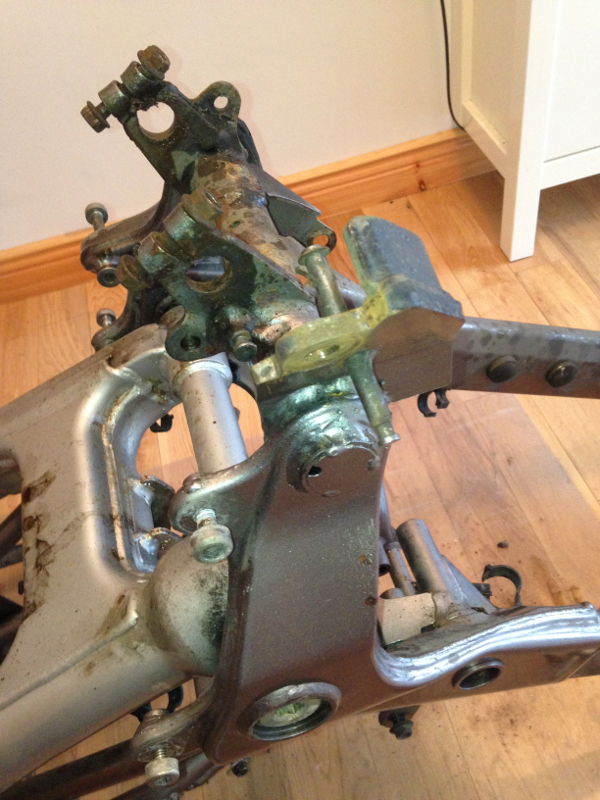
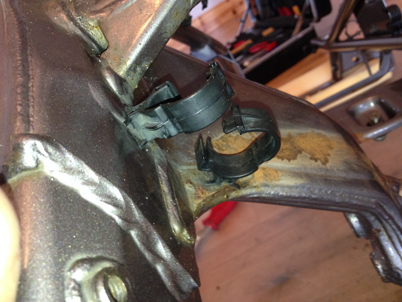
Day 19 was another short one. With the bike stripped to just the frame, the only rust I'd come across was one large patch just above the swing arm pivots. This area of the Deauville is the most prone to rust because the rear mud guard doesn't come down far enough to stop mud and debris from splashing onto the swingarm and shock absorber etc. The one patch of rust on my frame, however, looked like it had been accelerated either mechanically or chemically because everywhere else in that area was perfect. My guess is that it was accelerated mechanically, by the overflow and breather hoses that run beside it, because it's in a place where a spillage can't fall on it. The frame is upside-down in the photo, so you can image with the frame the right way up, nothing could spill onto the underside of it.
After wire-brushing and sanding the rusty patch, I sat down and seriously considered respraying the whole frame. The cost of getting a small amount of paint the right colour wouldn't be much, but it would mean another full day sanding to prepare for painting. Then spraying the colour, allowing to dry, then lacquering and allowing to dry. I decided it was time to get a grip of myself and stop being such a perfectionist. I had an aerosol can of silver/grey paint that wasn't the same colour, but was close enough, considering I was going to be spraying it onto a part of the frame that will never be seen. I sprayed the bare metal with it, just to provide some protection from rust.
Day 20
As they say in the manuals, "Installation is the reverse of removal".
Day 20 was the 1st of March. Originally, I had been aiming to be finished by the 1st of March, but I made the decision to do a bit extra from time to time, such as spraying the forks, swingarm etc, knowing that the bike would be off the road until after the 1st of March.
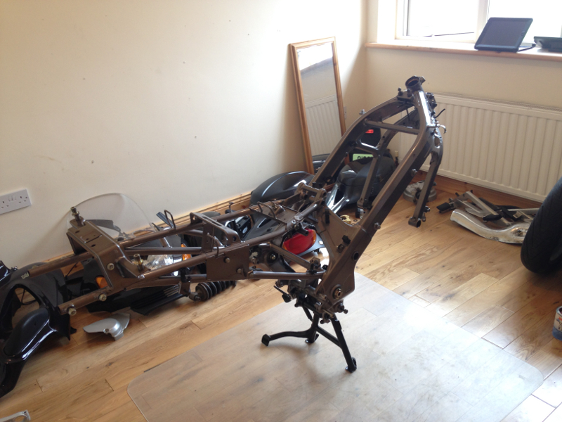
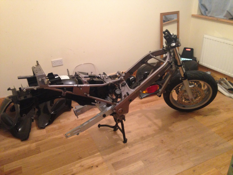
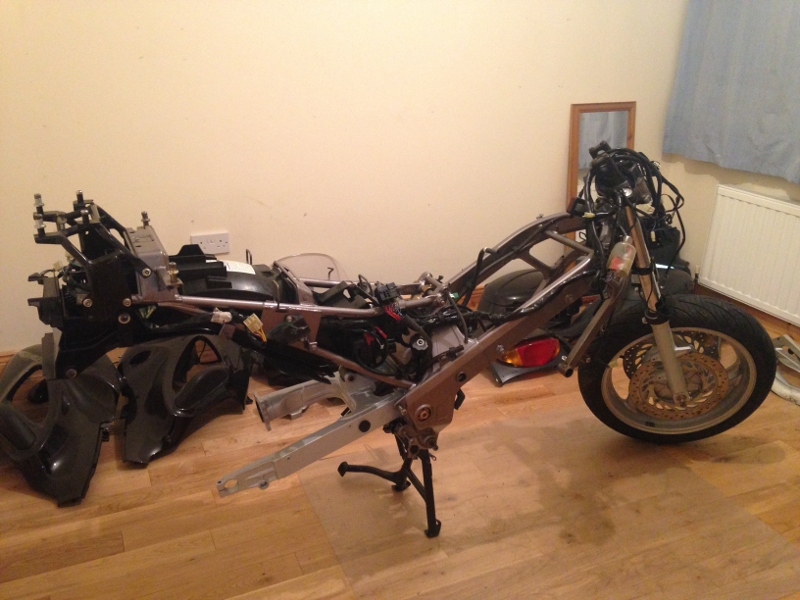
This is what the bike looked like at 10:00 on the morning of the 1st of March, before I started to assemble it again:
As I reassembled the bike, I cleaned, greased and adjusted everything. I scrubbed all the bolts etc with a drill-mounted wire brush. I coated all bolts, washers, pivots etc with copper grease, unless they were in contact with rubber, which the copper grease would damage. In that case, I used silicone grease. I coated all electrical contacts with contact grease before connecting them. Any parts that were originally bare metal, I coated in ACF 50 to protect them from corrosion. I sprayed small clips and brackets for holding hoses, cables etc with black paint from an aerosol can if the original paint was damaged. I treated all plastic and rubber parts with Autoglym Vinyl and Rubber Care. I washed painted parts if they were very dirty, or wiped them with a cloth after spraying Meguiars Ultimate Quik Detailer on them, if they were just dusty.
The first parts on were the centre stand and side stand:
Then I cleaned the swing arm bearings with petrol, allowed them to dry, then installed them and greased them with standard mineral grease. With the bearings in place, I installed the swingarm. This was where I needed the extra socket welded on to the side of the socket I cut specifically for the swingarm lock nut. I had to tighten the pivot to a certain pre-load (torque), then hold it still by putting an Allen key through the hole in the lock nut socket and use a torque wrench on the second socket to tighten the lock nut to the specified torque. I found it awkward to hold the Allen key still and apply enough torque to the torque wrench without the frame falling over. I'd say it would be easier on a full bike because it would be heavy enough to stay in place. I ended up holding the Allen key with my left hand, the frame with my right, and using my right knee to push down on the torque wrench.
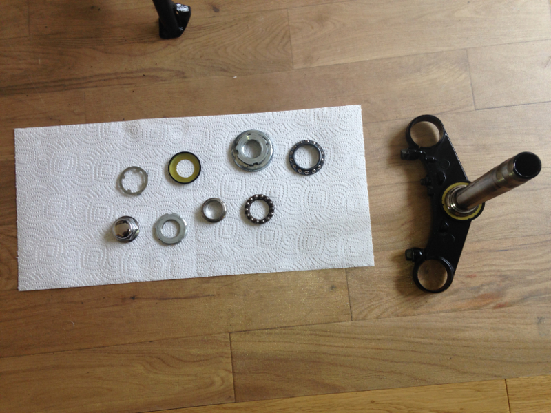
Here are the steering head bearings and the steering stem laid out after being cleaned with petrol, ready to be installed:
I installed, greased and adjusted the steering stem. Then I installed the forks. I washed the front wheel bearings in petrol, greased them and installed the wheel:
Next I fitted the rear shock absorber:
And the rear mud guard (main section):
Day 21
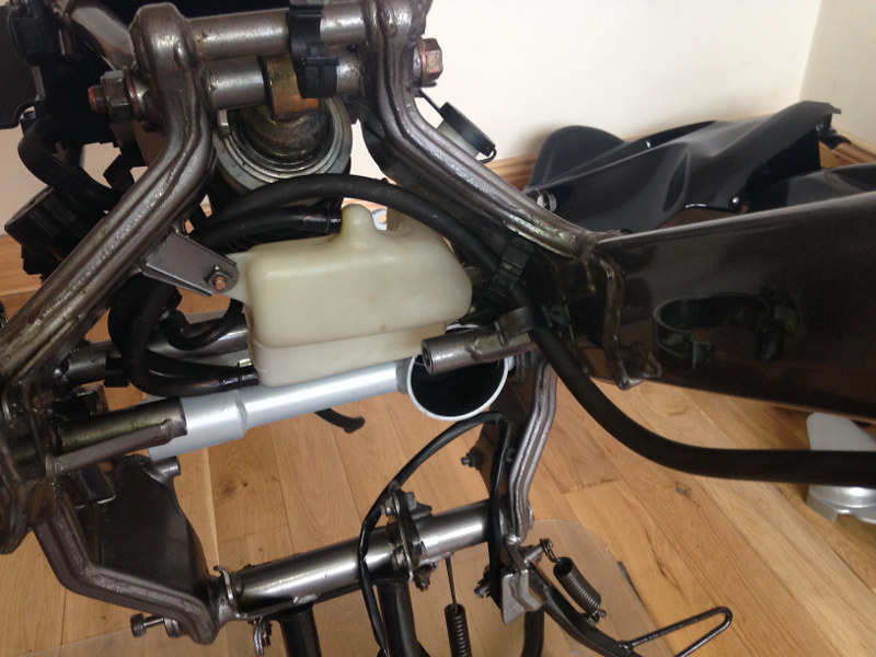
Next day, I washed out the coolant reservoir, cleaned and installed it:
Then I installed the rear cowl bracket:
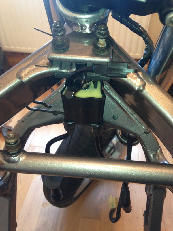
Front ignition coil:
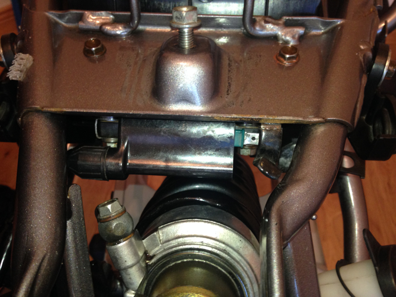
Rear ignition coil:
Fuel pump and new fuel filter:
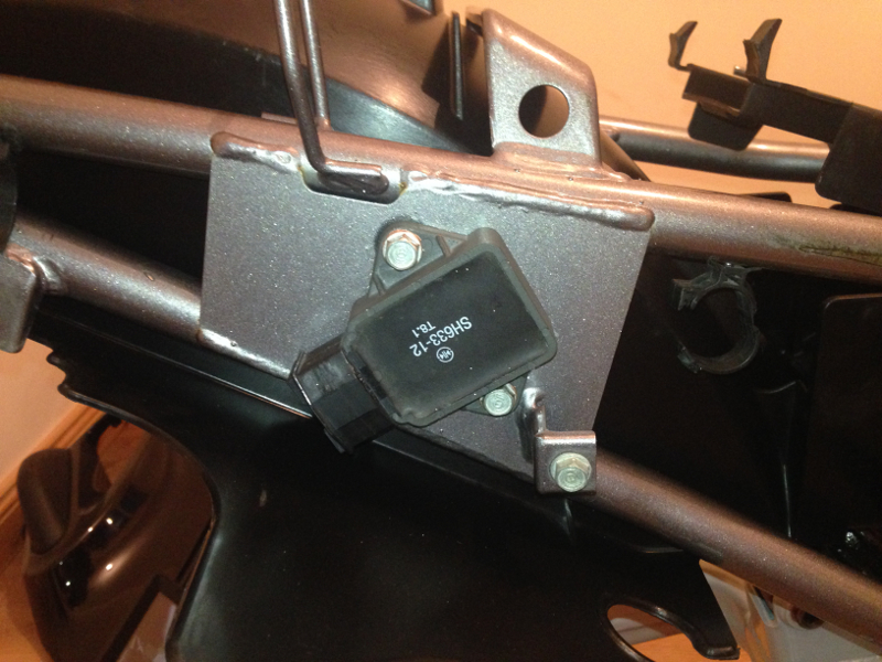
Regulator/rectifier:
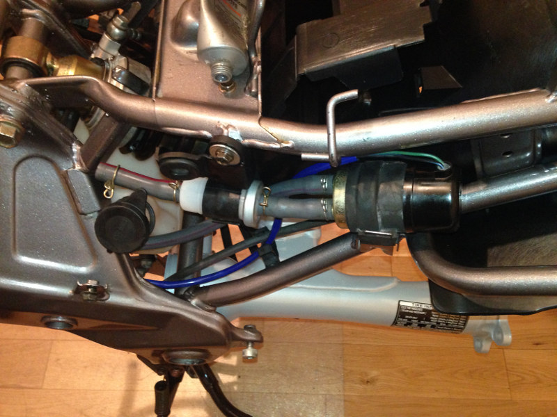
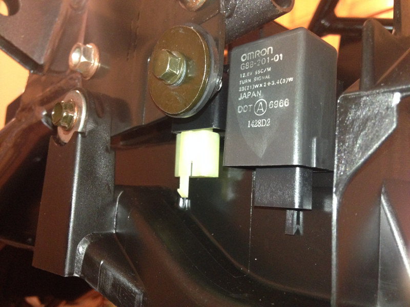
Turn signal relay and fuel cut-off relay:
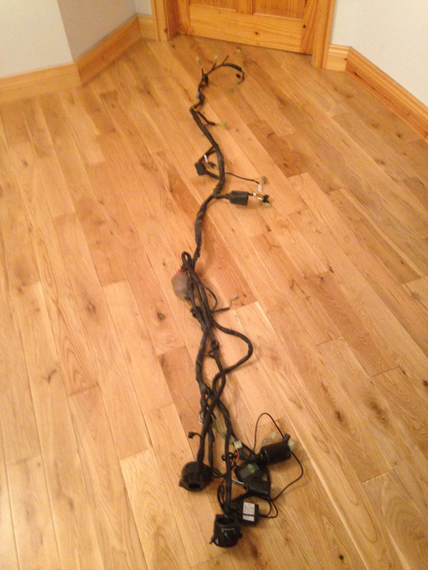
Here's the wiring loom before I started cleaning it. It looks like it should take about five minutes to clean. It took me two hours with a microfiber towel and a lot of Autoglym Vinyl and Rubber Care to clean every wire and connector on it.
Wiring loom installed on the bike:
16 March 2014
Day 22
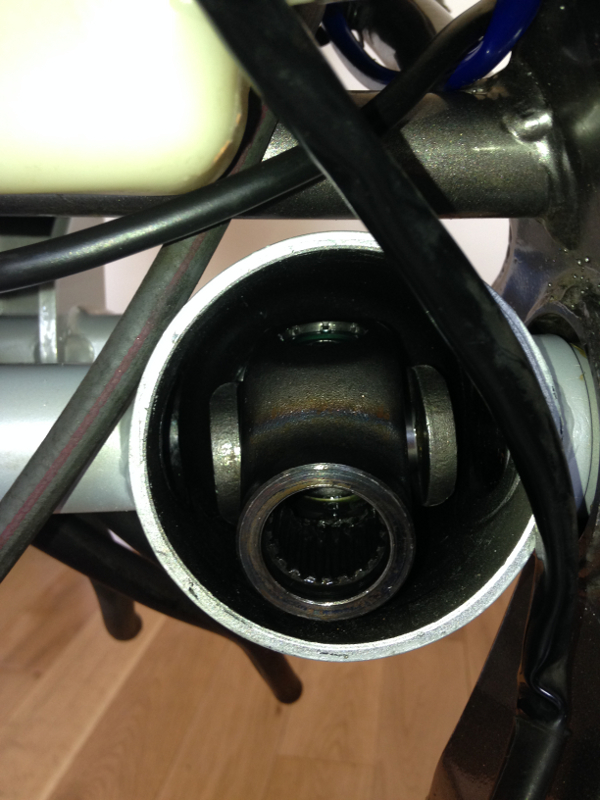
The Haynes manual says that you should install the universal joint on the drive shaft after installing the engine. This may have been possible on one of the older models that the Deauville is based on, but the swingarm on the Deauville has a "neck" where the universal joint meets the drive shaft, which means the UJ can't be installed from the rear of the swingarm. So, thinking I was smart, I put the universal joint into the swing arm and attached the drive shaft to it before installing the engine:
After struggling to get the engine out of the frame before, I decided that the easiest way to maneuver it back into the frame was to rest it on a jack, then simply lift the bike and drop it over the engine. This worked quite well, but only because the bike had so little on it.
After about two hours of nearly going insane, I finally gave up trying to get the universal joint to slide onto the output shaft of the engine. It has to be perfectly aligned to slide on and unless you are very lucky, you won't get that to happen by trying to move the universal joint around with the drive shaft and sticking the tips of your fingers under the boot to guide it on. It always feels like you are just about to get it on, but just not quite lined up. That lead me to keep trying for as long as I did. In the end, I had to unbolt the engine again, take it out, put the universal joint onto the output shaft of the engine and put the engine back in and bolt it in place. It was then quite easy to slide the drive shaft into the universal joint from the end of the swing arm.
21 March 2014
Day 23
With the drive shaft in place in the swing arm, the next part I fitted was the final drive hub. I only loosely fitted the four nuts that hold it in place, so that I could move it a little to make fitting the rear wheel a little easier:
After cleaning and re-greasing the rear wheel bearings, I fitted the wheel and the bracket for the rear brake caliper.
Next on was the handlebars:
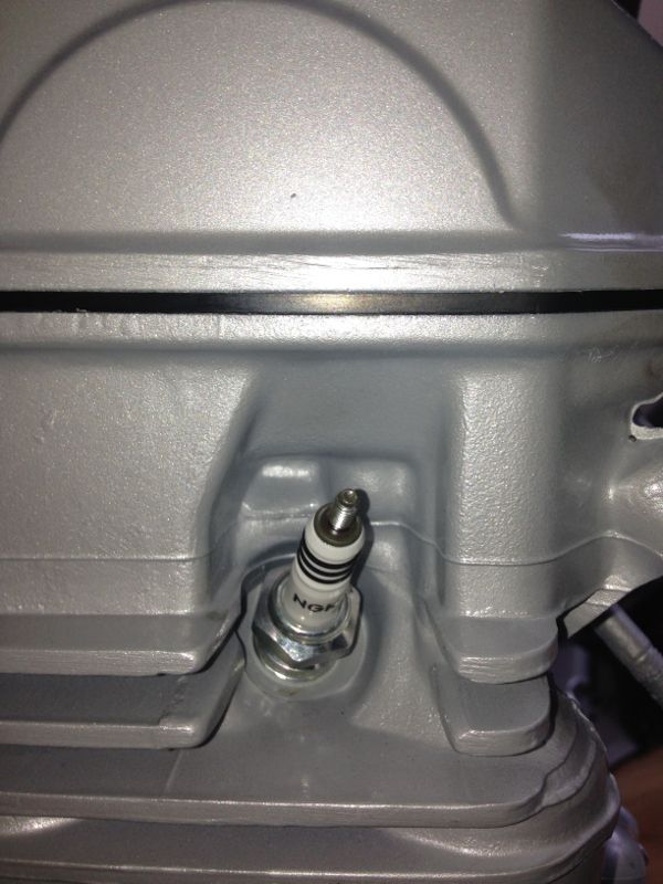
I also decided to fit the new NGK iridium-tip spark plugs, while I had easy access to them. I decided to go with DPR9EIX-9, which are the iridium version of what Honda recommend if you do more extended, higher speed riding.
Day 24
I spent a lot of time cleaning and scrubbing the brake calipers before fitting them. I removed the pads, and used a wire brush to scrub off a lot of the crap, being careful not to scrub the rubber boots on the pistons. I used a lot of brake cleaner and paper towels and finally had the calipers as clean as I wanted. I then used brake caliper grease to grease all the moving parts and the sliders where the pads slide before refitting the pads. I also emptied the brake fluid out of the master cylinders. Then I cleaned the brake hoses with Autoglym Vinyl and Rubber Care, while checking them for any damage or signs of wear. I fit the front brakes first:
With the handlebars in place, I now had somewhere to mount the front brake master cylinder and lever, as well as the handlebar switches:
After filling the front brake fluid reservoir with fluid, I bled the brakes using the old school method of pulling the lever, opening the bleed nipple, closing the bleed nipple and releasing the lever. I had a clear rubber hose from the bleed nipple going into a jar. I continued to bleed the brakes and adding fresh fluid to the reservoir, until the fluid coming out through the clear tube was new and clean. I started with the caliper furthest from the master cylinder, which is the offside (right-hand) one, then did the nearside one. Even after alternating back and forth between the two, there always seemed to be more air in there and I couldn't get the lever as firm as I'd like. Finally, after I'd gotten out as much air as I could, I used a tip I got on http://deauvilleuk.org/ and pulled the lever in hard, then strapped it to the handlebar and left it overnight, with bars turned so that the reservoir was higher than the banjo bolt where the hose is connected to it. This keeps the non-return valve (if there is one fitted) open, allowing any air in the system to slowly rise to the top overnight. When I checked it in the morning, I had a good firm brake lever.

Day 25
Before fitting the rear brakes, I needed to fit the right hand footpeg hanger, so that I had somewhere to mount the brakes. I cleaned the peg hanger and polished up the aluminium. I was using Autoglym Metal Polish. I found that the polish lifted the dirt from the aluminium very well, but because the aluminium is slightly textured, when I wiped the surface, I simply rubbed the dirt back into the texture of the aluminium. No matter how much polish and paper towels I used, the paper towel always came away black and the aluminium didn't look much cleaner. Finally, I found the quickest way to polish it was to rub the polish on a spot of the aluminium, and while the polish was still a bit wet, spray it off with brake cleaner. It took a full can of brake cleaner to clean one of the peg hangers, but I think the results were worth it.
 The metal gets VERY cold to handle when that amount of brake cleaner evaporates off it. There was a whitish residue on the metal afterwards, but this easily polished off with a microfiber towel. To help keep the aluminium clean, I then protected it with Wolf's Hard Body.
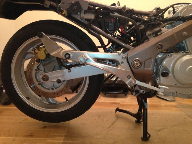
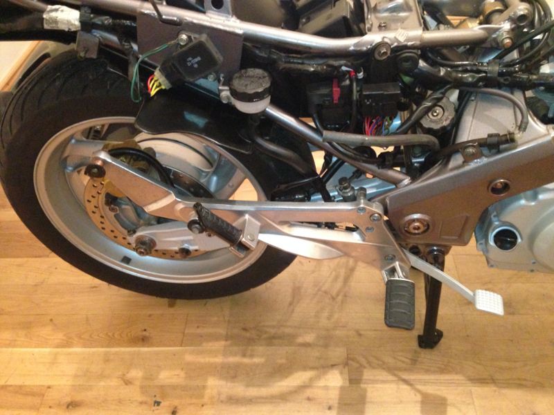
With the right foot peg bracket installed, I was then able to fit the rear brake system and the right hand foot pegs:
I filled the rear brakes with fresh brake fluid and bled them the same was as I did the front. The rear brakes were easier to bleed. I presume this is because there is only one caliper.
21 March 2014
Day 26
On Day 26, I fitted any screws and bolts that I had removed from the engine when I was painting it. Then I cleaned and fitted the front engine hanger (frame cross-member).
Day 27
The next day, I cleaned and fitted the secondary air system hoses and control solenoid, as well as connecting all the cooling hoses to the engine:
I removed the fan from the radiator, cleaned it, cleaned the radiator, refitted the fan and mounted the radiator to the engine. I also cleaned the chrome pipes by polishing them up with 000 grade wire wool, followed by a quick rub of chrome polish.
Then I fitted the left and right engine protectors:
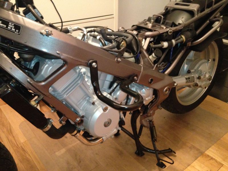
Day 28
I fitted the carburettors next. This involved mounting them on the engine, then adjusting the throttle cables (both pull and push cables), as well as the two choke cables and connecting the fuel feed hose and overflow hose. This is a time consuming job, because even routing the cables correctly, so that the don't interfere with the travel of the handlebars is more complicated than it sounds.
Day 29
I fitted the clutch lever and cable one morning before leaving for work, and adjusted the amount of free play in the cable:
That evening, when I got home, I polished the downpipes with 000 grade wire wool and chrome polish, then fitted them to the engine, using new exhaust port gaskets:
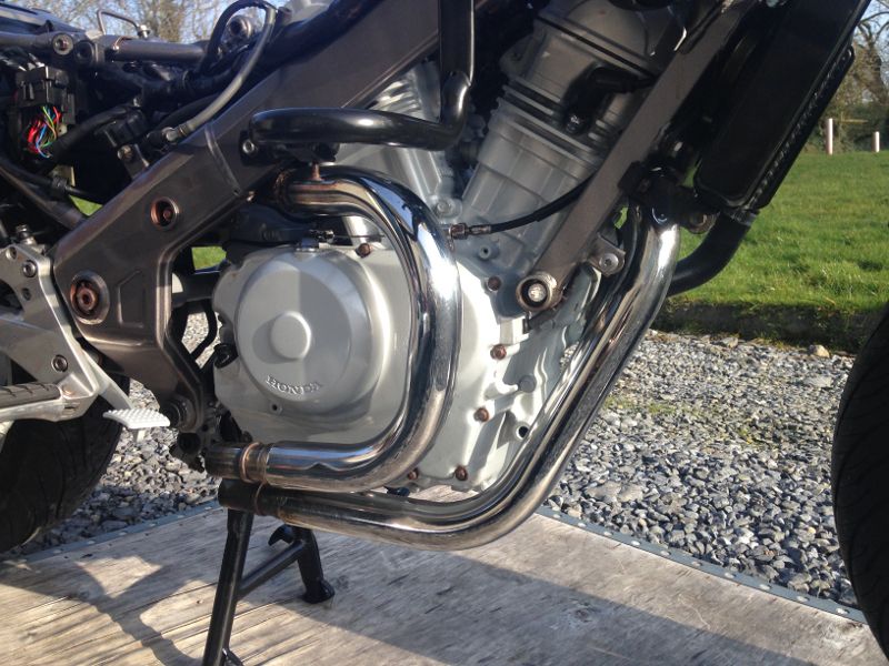
I had cleaned the rusting parts of the muffler the night before, and painted it with matt black stove paint. I fitted new gaskets where the downpipes meet the muffler and installed the muffler, after polishing the chrome in the usual way:
Day 30
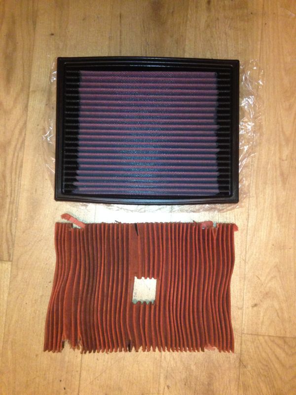
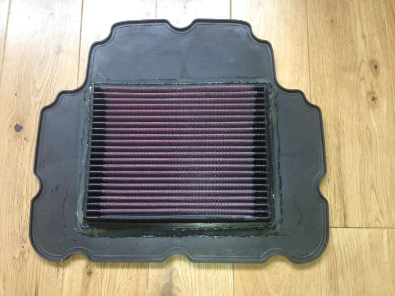
Air filters for the 650 Deauville are ridiculously expensive. The main reason for this is that the filter element is surrounded by an odd-shaped piece of plastic. The cheapest I've seen them online is about €34. For that reason, as well as wanting to let the engine breathe more easily, I decided to manufacture a home-brew K&N filter for it (K&N don't make air filters for the 650 Deauville). I measured the size of the paper element on my old air filter and after trawling through the K&N website, I found that the K&N filter for a 1993-2000 1.2 Opel Corsa was the closest in size. (K&N part number: 33-2098). Here's the K&N filter beside my old paper element, after I cut the element out of the plastic surround:
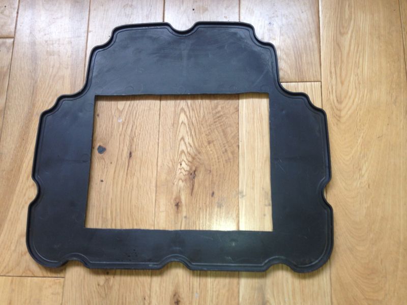
After cutting out the paper element, I had to widen the hole slightly on the plastic surround of the old filter:
I then had to cut about 5mm off the rubber surround of the K&N filter, because otherwise it would be a little too high. This was harder than I imagined because the rubber is too robust to be cut with a sharp knife. I ended up cutting it with a hacksaw, but it was quite difficult because the rubber kept flexing as I tried to cut it. I carefully aligned the K&N filter with the hole in the plastic surround and glued it in place using hot glue. I wondered if hot glue would melt when the engine was hot, but after checking online, I found that the melting point for low temperature glue sticks is 180°-200°. If the part of the engine between my legs gets that hot, I've more to worry about than my air filter!

With my home-brew K&N filter finished, I fitted the instrument cluster bracket:
I then fitted the instrument cluster, connected any cables and fitted the speedometer cable:
I installed the battery and then switched on the ignition to check that all the electronics were working. I wasn't able to test the lights because I didn't have them installed yet, but the oil pressure switch and neutral switch seemed to be working, so I decided it was time to start the bike. I filled the cooling system with Motul Motocool Expert (yellow stuff) and filled the engine with Motul Technosynthese 10W40 semi-synthetic oil. The Motul engine oil smells delicious. It smells very like chocolate, I was almost tempted to taste it. I temporarily installed the air filter and petrol tank, said a little prayer and hit the start button:
As you can see, she started, ran for a little bit, then died. Just after I stopped videoing, I noticed a strong smell of petrol and heard a gently dribbling noise. I'd forgotten to close the bleed screw on the float bowl of one of the carburettors.

After closing the bleed screw on the float bowl, the bike would start, but wouldn't idle like it had in the video above. After trying a few times, I gave up for the night.
EDIT:
Although it looks like I'm running an engine indoors, the rear half of the bike is sticking out the front door, so the exhaust fumes aren't coming into the house.
21 March 2014
Day 31
Day 31 was my birthday, 15th of March. I had hoped to have the bike on the road by that weekend, so I could go away on it for the long weekend, but I figured if I got out on the bike at all that weekend, I'd be happy, so I got up at about 07:00 and got to work.
First thing I did was to fill the final drive hub with Mobil 75W90 gear oil. I then took the bike outside and tried to figure out why it wouldn't idle. It would run okay above 2,500 rpm, but was a little lumpy. I figured that the problem must be fuel related. I didn't want to start overhauling the carburettors, because that would almost be a project in itself. I took them off, had a quick look at them, checked that there wasn't anything obvious wrong and put them back on again. After playing with it for a while, I noticed that the piston in the left-hand (rear) carburettor wasn't opening as much as the other one when the engine was revving. I watched it more closely and noticed petrol coming out of the passages beside the left-hand air intake and realised that the bowl for that carburettor was overflowing. I opened the float bowl, removed the float and float needle valve, cleaned them and refit everything. I put the carbs back on and it ran perfectly. I took it for a spin down the quiet bog road near my house to check that everything was working okay before starting to cover everything up and to get the engine up to operating temperature for setting the idle and synchronising the carburettors. I was delighted with it. The bike was much more responsive and smooth. Even the gear changes were easier and smoother.
To balance the carburettors, rather than using vacuum gauges, I use a simple homemade system that I found plans for online. I made it using old parts out of equipment I service at work. It doesn't matter what the vacuum actually is in the carburettors, as long as it's the same in both. I had to buy the little adapters to screw the tubing into the carburettors, but the rest is all made from stuff I would have been throwing out otherwise. Two glass bottles, two rubber bungs, and various bits of tubing. The liquid in the bottles is a dye we use for testing machines, which I added to water to make it easier to see. The system is simple. A tube running from the bottom of one bottle, out through the bung, in through the bung of the other bottle and down to the bottom. This tube allows liquid to flow from one bottle to the other if there is a difference in pressure. There's a second tube connected to the very top of each bottle. The end of each of these tubes is screwed on to the vacuum take-off on one of the carburettors. The total amount of liquid in the two bottles should fit into one bottle, without reaching the upper tube. If the liquid can reach the upper tube, and you aren't paying attention, the vacuum in the carburettors could suck liquid into the engine. When the engine is running, if the vacuum is equal, there will be equal vacuum in each bottle and the liquid will stay level. If there is a difference, the liquid will flow into the bottle with the higher vacuum. I prefer this system to using vacuum gauges because it's far more sensitive and you can get a much better synchronisation.
Here is my system connected to the bike. I have a funnel connected to the fuel pipe, because the tank needs to be removed when synchronising the carbs:

When I started the bike first, it emptied the liquid from one bottle to the other in a few seconds, even though the bike seemed to be running quite well. Balancing the carbs very accurately takes a lot of patience. Once you get close, even leaning the weight of the screwdriver on the screw makes a difference.
Here's a video of the bottles when the carbs are close to being balanced, but not quite right:
As you can see, the bottle on the right has a stronger vacuum, so the liquid flows into it from the other bottle.
The next video is of the final sychronisation. If you look closely, you will see that the level in the right hand bottle goes up a little, but after an hour of tweaking, that's as close as I could get it. Literally letting the weight of the screwdriver on the screw was having a bigger effect than that. Also, I noticed that the level in the bottles tended to fluctuate up and down a little anyway as the engine was running, so if that video was longer, you would see the level drop back down again.
With the carburettors synchronised, I just had to finish putting the bike back together. I thought throwing the fairings on would take me about two hours, but because I was cleaning them inside and out before fitting them and wiring brushing the screws and greasing them, it took a lot longer.
I cleaned up the air filter housing and installed it:
Fitted the front mud guard:
Petrol tank and rear cowl:
Right-hand luggage box:
Right-hand pillion grab rail:
Left-hand luggage box:
Left-hand pillion grab rail:
Rear mudguard (rear section):
Upper fairing and wind screen, including front lights:
Left-hand pillion foot peg (don't ask me why I didn't fit it until now.
 )
)
Right-hand middle fairing:
Left-hand middle fairing:
Middle fairing inner covers:
And finally, at 02:30 in the morning, the seat:
When I met Paul (Phew) earlier in the year, he told me that if the engine protectors would fit through the front door, the rest of the bike would. As I went to bed that night, I was hoping he was right, or I would have to do like Henry Ford did, and knock the wall around the front door to get the bike out, because I wasn't going to start taking bits off the bike again for a while.
If you like the blog and would like to be notified when I post new content, you can subscribe to my mailing list.